
SLIDE 1
Antonio Corradi Academic year 2018/2019 Goals, Basics, and Models
University of Bologna Dipartimento di Informatica – Scienza e Ingegneria (DISI) Engineering Bologna Campus Class of Infrastructures for Cloud
Computing and Big Data M
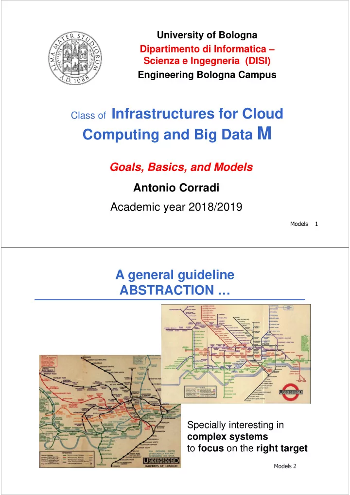
Models 1 Models 2