chapter 16 p 16
play

Chapter: 16 p 16 LTE Time-Frequency structure Downlink L1/L2 - PowerPoint PPT Presentation

3G Evolution Outline Chapter: 16 p 16 LTE Time-Frequency structure Downlink L1/L2 control signaling/processing Donwlink Transmission Donwlink Transmission Downlink transport channel processing Scheme Multi-Antenna


  1. 3G Evolution Outline Chapter: 16 p 16 • LTE Time-Frequency structure • Downlink L1/L2 control signaling/processing Donwlink Transmission Donwlink Transmission • Downlink transport channel processing Scheme • Multi-Antenna transmission • MBSFN transmission Department of Electrical and Information Technology The Date 3G Evolution - HSPA and LTE for Mobile Broadband 1 The Date 3G Evolution - HSPA and LTE for Mobile Broadband 2 Overall Time-domain structure Overall Time-domain structure • The radio frame in LTE is defined as blocks of 10 ms 
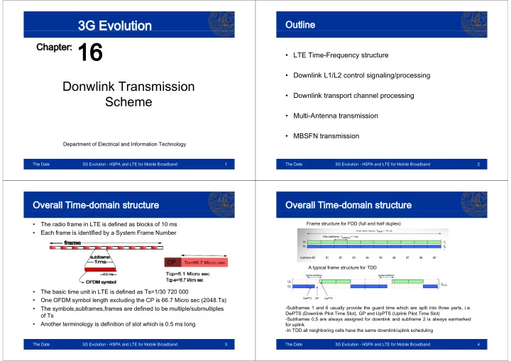
Frame structure for FDD (full and half duplex) • Each frame is identified by a System Frame Number E h f i id tifi d b S t F N b A typical frame structure for TDD • Th The basic time unit in LTE is defined as Ts=1/30 720 000 b i ti it i LTE i d fi d T 1/30 720 000 • One OFDM symbol length excluding the CP is 66.7 Micro sec (2048.Ts) • The symbols,subframes,frames are defined to be multiple/submultiples The symbols,subframes,frames are defined to be multiple/submultiples -Subframes 1 and 6 usually provide the guard time which are split into three parts, i.e. y p g p p , DwPTS (Downlink Pilot Time Slot), GP and UpPTS (Uplink Pilot Time Slot) of Ts -Subframes 0,5 are always assigned for downlink and subframe 2 is always earmarked • Another terminology is definition of slot which is 0.5 ms long for uplink -In TDD all neighboring cells have the same downlink/uplink scheduling In TDD all neighboring cells have the same downlink/uplink scheduling The Date 3G Evolution - HSPA and LTE for Mobile Broadband 3 The Date 3G Evolution - HSPA and LTE for Mobile Broadband 4

  2. Time-Frequency Grid Time-Frequency Grid • Subcarrier spacing of 15 KHz (7.5 KHz in MBSFN mode) • • One resource block consists of 12 consecutive subcarriers and stretches for 7 One resource block consists of 12 consecutive subcarriers and stretches for 7 OFDM symbols (in case of short cyclic prefix) • Resource elements, one subcarrier during one OFDM symbol R l b i d i OFDM b l • One resource block consists of, – 72 RE in case of normal CP – 84 RE in case of extended CP The Date 3G Evolution - HSPA and LTE for Mobile Broadband 5 The Date 3G Evolution - HSPA and LTE for Mobile Broadband 6 Time-Frequency Grid Time-Frequency Grid Cyclic Prefix (CP) Cyclic Prefix (CP) • The sampling rate is fs=15000.Nfft which is a multiple/submultiple of the WCDMA/HSPA chip rate WCDMA/HSPA chip rate • There are two CP modes corresponding to different system configuration • Nfft can be in any of the following, - Normal cyclic prefix is 160.Ts=5.1 Micro sec – 128, 256, 512, 1024, 2048 - Extended cyclic prefix is 512.Ts=16.7 Micro sec • • This makes it easier to have terminals supporting all these standards This makes it easier to have terminals supporting all these standards • Why two different CP? • The central subcarrier (DC-subcarrier) is not used for downlink to avoid – In case of larger cells with extensive delay spread, a longer CP is usually beneficial In case of larger cells with extensive delay spread, a longer CP is usually beneficial interference (e.g. local oscialtor leakage) unless the performance is more affected by noise! – in MBSFN, CP not only covers the channel dispersion but also the timming • LTE physical-layer specifications allow downlink to consist of 6 up to 110 p y y p p difference between transmitters invloved in broadcast resource blocks (BW 1MHz-20MHz) • In case of normal CP, the first OFDM symbol in each slot has a somewhat larger length so the overall slot length becomes and exact multiple of Ts larger length so the overall slot length becomes and exact multiple of Ts • • Note: despite the above fact the radio frequency requirements are (initially) Note: despite the above fact the radio frequency requirements are (initially) defined for a limited set of transmission bandwidth (e.g. Max no. of RB is 100) • In a frame, subframes could have either/both normal or/and extended CP (e.g. In case of MBSFN combined configuration could happen) In case of MBSFN combined configuration could happen). The Date 3G Evolution - HSPA and LTE for Mobile Broadband 7 The Date 3G Evolution - HSPA and LTE for Mobile Broadband 8

  3. Downlink Reference Signals Cell-specific downlink RS (Pilots) (Pilots) • The reference pilots are inserted assuming the full BW, i.e. 110 assuming the full BW i e 110 • To assist channel estimation reference signals are inserted at specific locations resource blocks. Thus, the pilots in in each resource block the central part of the band will always be the same � fascilitates always be the same � fascilitates • Three types of reference signal distributions are defined for LTE, decoding of BCH info • Pilot pattern of each cell has a cell- specific configuration specific configuration – Cell specific downlink RS (Reference Signals) are inserted in every downlink Cell specific downlink RS (Reference Signals) are inserted in every downlink subframe and span the entire downlink cell BW • The depicted pattern is only one out of 6 possible frequency shifts of pilot – UE-specific RS used in DownLink-Shared-CHannel (DL-SCH) and are intended for UE specific RS used in DownLink Shared CHannel (DL SCH) and are intended for patterns patterns specific terminals. They are transmitted in non-codebook-based beam forming where • each cell has a specific pilot pattern terminal is not aware of what precoding matrix has been applied to the data corresponding to its cell identity • There are 504 cell identities defined Th 504 ll id titi d fi d – MBSFN reference signals, as evident from the name, are used in MBSFN for LTE. Thus, each frequency shifted transmission pilot pattern covers 84 different cell identities identities The Date 3G Evolution - HSPA and LTE for Mobile Broadband 9 The Date 3G Evolution - HSPA and LTE for Mobile Broadband 10 Cell-specific downlink RS-Multiple Cell-specific downlink RS antenna ports antenna ports • LTE benefits from MIMO scheme • In specifications the term antenna port is prefered over antenna since two/multiple physical antennas can transmit the same information and hence make one antenna port • Smart assigning of pilot patterns in neighboring cells reduces the interference caused on the pilot positions assiged to each individual cell This becomes caused on the pilot positions assiged to each individual cell. This becomes specially handy when pilots are power boosted to fasciliated better channel • Each antenna port has a specific pilot pattern assigned to it. Thus, the terminal can estimation estimate the downlink channel corresponding to each transmit antenna independantly • The resource elements corresponding to pilots of each antenna port don’t carry any • In the so called cell search procedure (Chapter 18) the terminal detects the information for the resource blocks scheduled for other ports physical cell identity as well as the begining of pilot sequences • In case of 4 antenna ports the third and fourth antenna ports have less pilot density which • To determine the cell BW, BCH information (e.g. BW) is provided in the central comes with the following pros/cons, part of BW where terminal does the channel estimation without having a prior – the reference signal overhead is reduced as an advantage knowledge of cell BW k l d f ll BW – the channel estimation and tracking of channel variations degrades as a consequence Note: 4 antenna spatial multiplexing is usually used in low mobility scenarios! The Date 3G Evolution - HSPA and LTE for Mobile Broadband 11 The Date 3G Evolution - HSPA and LTE for Mobile Broadband 12

  4. Cell-specific downlink RS-Multiple Cell-specific downlink RS-Multiple antenna ports antenna ports antenna ports antenna ports The Date 3G Evolution - HSPA and LTE for Mobile Broadband 13 The Date 3G Evolution - HSPA and LTE for Mobile Broadband 14 UE-specific downlink RS UE-specific downlink RS • • The terminal is informed by the network if the DL SCH is done through cell The terminal is informed by the network if the DL-SCH is done through cell- • UE-specific transmission is referred to specific antenna ports or antenna port 5 beam-formed transmission intended for a specific terminal/group of t terminals i l • The beam forming is based on non-codebook configuration in which the base station doesn’t convey the precoding matrix to the UE/Ues • Just as data is beam-formed, pilots need also beamforming as a result of which UE-specific reference signals • Thus the terminal needs to know the channel experienced by the beamformed are created data • Transmission incompassing UE- specific RS is also called transmission • The pilots will go through the same beamforming applied to data before using antenna port 5 transmitted to UE • Piolts corresponding to antenna port 5 don’t collide with pilots transmitted on cell-specific RS The Date 3G Evolution - HSPA and LTE for Mobile Broadband 15 The Date 3G Evolution - HSPA and LTE for Mobile Broadband 16

Download Presentation
Download Policy: The content available on the website is offered to you 'AS IS' for your personal information and use only. It cannot be commercialized, licensed, or distributed on other websites without prior consent from the author. To download a presentation, simply click this link. If you encounter any difficulties during the download process, it's possible that the publisher has removed the file from their server.

Recommend


More recommend