cds 140b control of bifurcations and limit cycles
play

CDS 140b: Control of Bifurcations and Limit Cycles Richard M. - PDF document

CDS 140b: Control of Bifurcations and Limit Cycles Richard M. Murray Caltech Control and Dynamical Systems February 2008 Goals Describe how bifurcations & limit cycles arise in engineering applications Review some tools for


  1. CDS 140b: Control of Bifurcations and Limit Cycles Richard M. Murray Caltech Control and Dynamical Systems February 2008 Goals • Describe how bifurcations & limit cycles arise in engineering applications • Review some tools for characterizing bifurcations and limit cycles • Show how feedback can be used for design of (nonlinear) dynamics Outline • Lecture 1: Introduction and background • Lecture 2: Analysis and control of bifurcations • Lecture 3: Modeling and control of limit cycles • Lecture 4: Describing function analysis http://www.cds.caltech.edu/~murray/wiki/cds140-bifctrl 
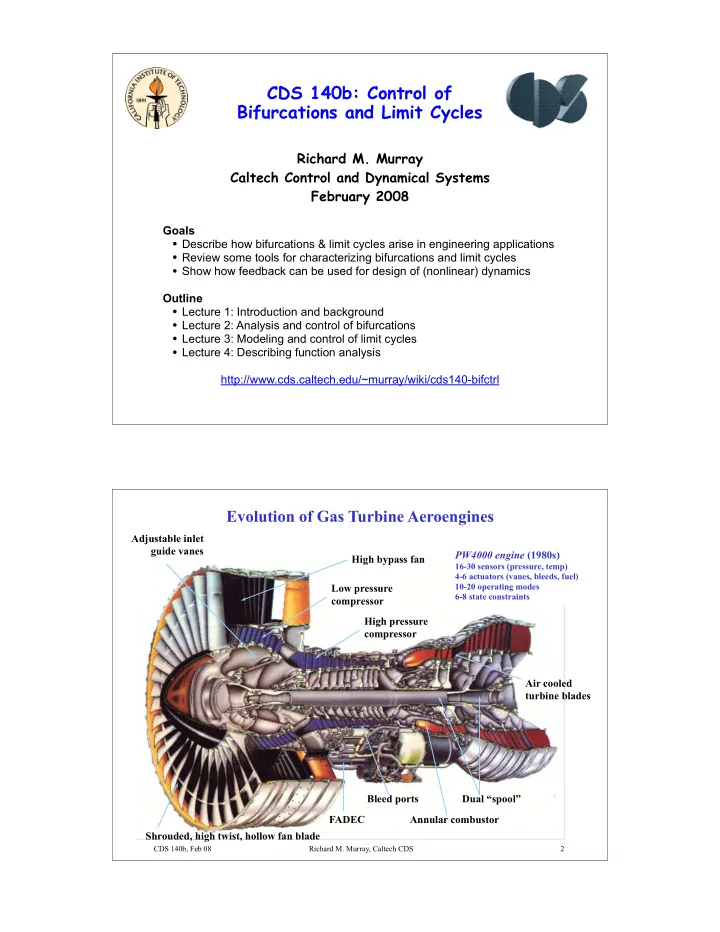
Evolution of Gas Turbine Aeroengines Adjustable inlet guide vanes PW4000 engine (1980s) High bypass fan 16-30 sensors (pressure, temp) 4-6 actuators (vanes, bleeds, fuel) 10-20 operating modes Low pressure 6-8 state constraints compressor High pressure compressor Air cooled turbine blades Bleed ports Dual “spool” FADEC Annular combustor Shrouded, high twist, hollow fan blade CDS 140b, Feb 08 Richard M. Murray, Caltech CDS 2

  2. Performance Limitations in Aircraft Engines Inlet separation Compressor stall, Combustion Jet noise, surge, flutter, HCF instabilities IR signature Afterburner Pratt & Whitney F100 engine Fan flutter, high Turbine tip clearance cycle fatigue Distortion tolerance, fan noise Inlet separation Flutter and high cycle fatigue � Separation of flow from surface � Aeromechanical instability � Major source of maintenance, failures � Possible use of flow control to modify Combustion instabilities Distortion � Large oscillations cannot be tolerated � Major cause of compressor disturbances � Typically discovered late in development Rotating stall and surge Jet noise and shear layer instabilities � Control using BV, AI, IGVs demonstrated � Gov’t regulations driving new innovation � Increase pressure ration � reduce stages CDS 140b, Feb 08 Richard M. Murray, Caltech CDS 3 Rotating Stall Dynamics Compression System Dynamics Emmons model (1952) Rotor Stator Duct Duct Throttle Compressor Plenum Pressure Rise � Mass flow CDS 140b, Feb 08 Richard M. Murray, Caltech CDS 4

  3. Impact of Stall and Surge on Engine Performance t i m i l y Stall point t i l i b t i a m t S i Pressure Ratio l g n i t a r e p Pressure Rise O Speed Hysteresis Mass flow Flow Rate Benefits of active control of stall/surge System performance limited by instability � 10% decrease in stalling mass flow can lead to 2% increase in fuel efficiency (!) � Number of rotors/stators required to deliver pressure set by instability limit � Requires system redesign, not retrofit � Hysteresis loop forces operation away � Complexity, weight, reliability are from peak pressure rise important (mostly unaddressed) issues CDS 140b, Feb 08 Richard M. Murray, Caltech CDS 5 Active Control Concepts: Stabilization + Bifurcation Control amplitude Stall cell Stall cell amplitude �� � � Hysteresis Region Hysteresis Region Stability Extension Eliminated Throttle Lines, � T Stable Equilibria Unstable Eq. � Stable Equilibria � � , e � c , e s i s R i R e � c e r u r u s s s e s e r Rotating Stall Equilibria P r Rotating Stall Equilibria P Mass Flow, � Mass Flow, � CDS 140b, Feb 08 Richard M. Murray, Caltech CDS 6

  4. Combustion Instabilities: Lean, Premixed, Liquid Fuel PW FT8 Pressure Flame wave, Front velocity fluctuation Thermoacoustic instability at lean limit � Positive feedback between heat release and acoustic oscillations CDS 140b, Feb 08 Richard M. Murray, Caltech CDS 7 Essential Physics (Culick Model) Murray, Jacobson, et al (ACC, 1998) Linear Acoustics ID Pressure Gain Flame wave, Front velocity fluctuation Phase Linear acoustics p Frequency G(s) 1.4 d 1.2 dt N d 1 Heat Release dt ~ 0.8 NL heat release u 0.6 0.4 q � � e s H( � ) 0.2 0 -30 -20 -10 0 10 20 30 Velocity CDS 140b, Feb 08 Richard M. Murray, Caltech CDS 8

  5. Combustion Instability Control Proscia, Cohen, Jacobson et al (UTRC) NO X limit -15 Peak Pressure Fluctuation (dB) Uncontrolled -20 Pressure limit -25 Piloted -30 Actively Controlled -35 -40 20 40 60 80 100 120 140 Modulation of main fuel flow NOx Emissions (ppm) � Modulate main fuel flow using combustor pressure -20 Uncontrolled � Simple control law (gain + phase) -30 Controlled provides significant reduction in Pressure (dB) -40 pressure oscillations -50 � Fundamental limits determined by actuator constraints (magn + BW) -60 -70 -80 100 150 200 250 300 Frequency (Hz) CDS 140b, Feb 08 Richard M. Murray, Caltech CDS 9 Rotorcraft Separation Control (DARPA MAFC) Must exploit dynamic effects to achieve low authority actuation Goal Technical Challenges � Alleviate separation as constraint on design / � High speed compressible flow performance for rotorcraft � Complex 3D geometries � Retreating blade stall � Actuator power and weight � Airframe separation � Dynamic modeling to guide design � Improved engine integration Approach � UAV performance � Prioritize & downselect applications Objectives � Minimize actuator authority � 10% maneuverability improvement � Model low-order dynamics of flow � 50% reduction in high speed drag physics � 20% fuel savings or +15 knot max speed � Optimize location, frequency, etc. Retreating blade stall Airframe separation Diffuser performance CDS 140b, Feb 08 Richard M. Murray, Caltech CDS

  6. Active Control of Separation Using Unsteady Forcing McCormick, Lorber et al (UTRC) Steady vs unsteady blowing UTRC/DARPA Airfoil Tests Steady slot blowing Small oscillatory blowing Lift coefficient Reflection of smoke Laser sheet Control intersection Control Control No control with airfoil off on on Source: Wygnanski, 1994 Separation reduced Separated flow � loss of lift Drag coefficient Open Questions � How much actuator authority is required Advantages of oscillating slot blowing (magn, rate, spacing)? � Zero mean actuation � What is the underlying mechanism that we are � 10X reduction in power exploiting? � Exploits natural flow instabilities � McCormick, Aerospace Sciences, Jan 00 CDS 140b, Feb 08 Richard M. Murray, Caltech CDS Cavity Flow Instabilities C. Rowley (Princeton), T. Colonius, D. MacMynowski, R. Murray (CIT), D. Williams (IIT) Phenomena � Shear layer instability above cavity Approach � Self-excited via acoustic reflections � Verify instability mechanism using CFD (Colonius, May 99) � Generates large oscillations � Build control-oriented model Applications � Capture essential physics � Landing gear, bomb bays � Integrate actuation, sensing � Railroad cars (?) � Test control in CFD, water tunnel CDS 140b, Feb 08 Richard M. Murray, Caltech CDS

  7. Common Features & Observations on Control of Fluids (ca 2001) 1. Effective control of flows in engineering applications relies on the Rotating stall existence of a low order phemonenon that control can affect Rotor stall � Limits in sensing and actuation will restrict us to these cases Cavity flows � Experiments leading theory; many examples with coherent structures Combustion 2. Actuator placement and limits are critical Bleed valves Air injection � Minimize spatial and temporal authority of actuators (and sensors) Slot blowing � Application specs include cost, weight, reliability, complexity, wiring Flap actuation � Exploit dynamics to achieve reduced authority control Fuel modulat’n 3. Stabilization of steady flows is not the most important problem Rotating stall Airfoil stall � Most examples give unsteady controlled behavior (eg, small oscillations) Cavity flows � Limited spatial authority often makes linearization uncontrollable Combustion 4. Need better tools Criticality ctrl � Data-driven, control-oriented modeling & analysis Fund. limits � Stabilization of unsteady flows � operability enhancement System ID � Need better tools for analysis and synthesis Robustness CDS 140b, Feb 08 Richard M. Murray, Caltech CDS 13 Bifurcations of Dynamical Systems Consider a family of differential equations: Defn The system has a bifurcation at µ = µ * if the flow of the system changes quantitatively at µ * . x e ( µ ) Example 1: exchange of stability µ Example 2: pitchfork bifurcation x e ( µ ) x e ( µ ) µ µ Supercritical Subcritical CDS 140b, Feb 08 Richard M. Murray, Caltech CDS 14

  8. Moore-Greitzer Model (1986) One mode expansion + Galerkin projection Pressure Rise, � Mass flow, � CDS 140b, Feb 08 Richard M. Murray, Caltech CDS 15 Linear Stability Analysis of MG-3 Model Linearization around J=0 equilibrium point: Slope of compressor characteristic Slope of throttle B = Greitzer B-parameter Stability conditions: Throttle Lines, � T Surge mode Unstable Eq. � Stable Equilibria � , e s i R Stall mode � c e r u s s e r Rotating Stall Equilibria P CDS 140b, Feb 08 Richard M. Murray, Caltech CDS 16

Download Presentation
Download Policy: The content available on the website is offered to you 'AS IS' for your personal information and use only. It cannot be commercialized, licensed, or distributed on other websites without prior consent from the author. To download a presentation, simply click this link. If you encounter any difficulties during the download process, it's possible that the publisher has removed the file from their server.

Recommend


More recommend