SLIDE 1
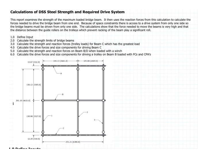
Calculations of DSS Steel Strength and Required Drive System
This report examines the strength of the maximum loaded bridge beam. It then uses the reaction forces from this calculation to calculate the forces needed to drive the bridge beam from one end. Because of space constraints there is access to a drive system from only one side so the bridge beams must be driven from only one side. The calculations show that the force needed to move the beams is very high and that the distance between the guide rollers on the trolleys which prevent racking of the beam play a significant roll. 1.0 Define Input 2.0 Calculate the strength limits of bridge beams 3.0 Calculate the strength and reaction forces (trolley loads) for Beam C which has the greatest load 4.0 Calculate the drive forces and size components for driving Beam C 5.0 Calculate the strength and reaction forces on Beam B/D when loaded with a winch 6.0 Calculate the drive forces and size components for driving a trolley on Beam B loaded with FCs and CPA's
1 0 Define Inputs
SLIDE 2
1.0 Define Inputs
Beams are stainless steel S8x18.4 ≔ AS8 ⋅ 5.4 in in2 ≔ qbeam = ⋅ ⋅ AS8 .283 ―― lbf lbf in in3 1.5 ―― lbf lbf in in ≔ Ix ⋅ 57.5 in in4 ≔ Sx ⋅ 14.4 in in3 ≔ r ⋅ 3.26 in in ≔ Z 16.5 in in3 ≔ T 6 in in ≔ tf ⋅ ― 7 16 in in ≔ tw ⋅ ― 1 4 in in Material - A36 ≔ fy 36 ksi ksi ≔ fu 50 ksi ksi ≔ E 29000 ksi ksi Geometry ≔ a 332.0 mm mm ≔ b 3305 mm mm ≔ c 3327 mm mm ≔ d 310 mm mm ≔ e 3661 mm mm ≔ f 2669 mm mm ≔ Lbridge = + e f 20.8 ft ft Length of beam ≔ spacingcpa 1.1 m Spacing between CPA supports 1 t 6 l ti f t ll /l d i t l f
SLIDE 3
≔ x1 = − ―― +f 2 ⋅ 2.5 spacingcpa 16.3 in x1 to x6 are locations of trolley/load points along the length of beam from one end ≔ x2 = − ―― + e f 2 ⋅ 1.5 spacingcpa 59.6 in in ≔ x3 = − ―― + e f 2 ⋅ 0.5 spacingcpa 103 in in ≔ x4 = + ―― + e f 2 ⋅ 0.5 spacingcpa 146.3 in in ≔ x5 = + ―― + e f 2 ⋅ 1.5 spacingcpa 189.6 in in ≔ x6 = + ―― + e f 2 ⋅ 2.5 spacingcpa 232.9 in in ≔ WCPA ⋅ 160 lbf lbf Weight of CPA ≔ WFC ⋅ 440 lbf lbf Weight of FC ≔ Wbeam = ⋅ qbeam Lbridge 380.8 lbf lbf Weight of bridge beam
2.0 Calculate Strength Limits of S8x14.5 beam
≔ γM0 1.0 ≔ γM1 1.0 ≔ γM2 1.25 ≔ ε = ‾‾‾‾‾‾ ―― 235 ―― fy 0.973
SLIDE 4
MPa MPa = ― T tw 24 = ⋅ 73 ε 71 = ⋅ 33 ε 32.1 Class 1 cross section ≔ Mc = ―― ⋅ Z fy γM0 49500 ⋅ lbf lbf ft
3.0 Calculate Reaction Forces and Stresses in CPA Support beam (C Beam)
Worst case is during installation and CPA carried total load of FC ≔ FCPA = + WCPA ⋅ 4 ⎛ ⎜ ⎝ ―― WFC 2 ⎞ ⎟ ⎠ 1040 lbf lbf Load from CPA strap onto bridge beam ≔ Ra ⋅ 1000 lbf lbf ≔ Rb 1000 lbf lbf ≔ Rc ⋅ 1000 lbf lbf ≔ y7 .1 in in ≔ y1 .1 in in ≔ y2 .1 in in ≔ y3 .1 in in ≔ y4 .1 in in ≔ y5 .1 in in ≔ y6 .1 in in = − − + ⋅ FCPA ( ( + + + + + x1 x2 x3 x4 x5 x6) ) ⋅ qbeam ――― Lbridge
2
2 ⋅ e Rb ⋅ Lbridge Rc 0.0 = + + Ra Rb Rc + ⋅ 6 FCPA ⋅ qbeam Lbridge = ――――― FCPA ⋅ ⋅ ⋅ 6 E Ix Lbridge ⎛ ⎝ − + ⋅ ⋅ −⎛ ⎝ ⋅ ⎛ ⎝ − 2 Lbridge x1⎞ ⎠ ⎛ ⎝ − Lbridge x1⎞ ⎠⎞ ⎠ x1 e ⎛ ⎝ ⋅ ⎛ ⎝ − Lbridge x1⎞ ⎠ e3 ⎞ ⎠ ⋅ Lbridge ( ( − e x1) )
3 ⎞
⎠ y1 = ――――― FCPA ⋅ ⋅ ⋅ 6 E Ix Lbridge ⎛ ⎝ − + ⋅ ⋅ −⎛ ⎝ ⋅ ⎛ ⎝ − 2 Lbridge x2⎞ ⎠ ⎛ ⎝ − Lbridge x2⎞ ⎠⎞ ⎠ x2 e ⎛ ⎝ ⋅ ⎛ ⎝ − Lbridge x2⎞ ⎠ e3 ⎞ ⎠ ⋅ Lbridge ( ( − e x2) )
3 ⎞
⎠ y2 = ――――― FCPA ⋅ ⋅ ⋅ 6 E Ix Lbridge ⎛ ⎝ − + ⋅ ⋅ −⎛ ⎝ ⋅ ⎛ ⎝ − 2 Lbridge x3⎞ ⎠ ⎛ ⎝ − Lbridge x3⎞ ⎠⎞ ⎠ x3 e ⎛ ⎝ ⋅ ⎛ ⎝ − Lbridge x3⎞ ⎠ e3 ⎞ ⎠ ⋅ Lbridge ( ( − e x3) )
3 ⎞
⎠ y3 = ――――― FCPA ⋅ ⋅ ⋅ 6 E Ix Lbridge ⎛ ⎝ + ⋅ ⋅ −⎛ ⎝ ⋅ ⎛ ⎝ − 2 Lbridge x4⎞ ⎠ ⎛ ⎝ − Lbridge x4⎞ ⎠⎞ ⎠ x4 e ⎛ ⎝ ⋅ ⎛ ⎝ − Lbridge x4⎞ ⎠ e3 ⎞ ⎠⎞ ⎠ y4
SLIDE 5
= ――――― FCPA ⋅ ⋅ ⋅ 6 E Ix Lbridge ⎛ ⎝ + ⋅ ⋅ −⎛ ⎝ ⋅ ⎛ ⎝ − 2 Lbridge x5⎞ ⎠ ⎛ ⎝ − Lbridge x5⎞ ⎠⎞ ⎠ x5 e ⎛ ⎝ ⋅ ⎛ ⎝ − Lbridge x5⎞ ⎠ e3 ⎞ ⎠⎞ ⎠ y5 = ――――― FCPA ⋅ ⋅ ⋅ 6 E Ix Lbridge ⎛ ⎝ + ⋅ ⋅ −⎛ ⎝ ⋅ ⎛ ⎝ − 2 Lbridge x6⎞ ⎠ ⎛ ⎝ − Lbridge x6⎞ ⎠⎞ ⎠ x6 e ⎛ ⎝ ⋅ ⎛ ⎝ − Lbridge x6⎞ ⎠ e3 ⎞ ⎠⎞ ⎠ y6 = ⋅ ――― ⋅ −qbeam e ⋅ ⋅ 24 E Ix ⎛ ⎝ + − Lbridge
3
⋅ ⋅ 2 Lbridge e2 e3 ⎞ ⎠ y7 = + + + + + + y1 y2 y3 y4 y5 y6 y7 ――――― ⋅ ⋅ −Rb e2 f2 ⋅ ⋅ ⋅ 3 E Ix Lbridge ≔ So Sol = Find Find ( ( , , , , , , , , , Ra Rb Rc y1 y2 y3 y4 y5 y6 y7) ) 1582.9 lbf lbf 4097.2 lbf lbf 940.8 lbf lbf 0 ft ft 0 ft ft 0 ft ft 0 ft ft 0 ft ft 0 ft ft 0 ft ft ⎡ ⎢ ⎢ ⎢ ⎢ ⎢ ⎢ ⎢ ⎢ ⎢ ⎢ ⎢ ⎣ ⎤ ⎥ ⎥ ⎥ ⎥ ⎥ ⎥ ⎥ ⎥ ⎥ ⎥ ⎥ ⎦ = + ⋅ 6 FCPA ⋅ qbeam Lbridge 6620.8 lbf lbf ≔ Ratrolley = So Sol ( (0) ) 1582.9 lbf lbf ≔ y1 = So Sol ( (3) ) −0.0364 in in Ra,Rb,Rc are reaction forces from Beam B to transverse beam -- these are the loads on each trolley supporting Beam B. Y1 to Y6 are the deformations caused by each load at trolley Rb ≔ y2 = So Sol ( (4) ) −0.1242 in in ≔ Rbtrolley = So Sol ( (1) ) 4097.2 lbf lbf ≔ y3 = So Sol ( (5) ) −0.1826 in in ≔ y4 = So Sol ( (6) ) −0.1902 in in ≔ Rctrolley = So Sol ( (2) ) 940.8 lbf lbf ≔ y5 = So Sol ( (7) ) −0.1355 in in ≔ y6 = So Sol ( (8) ) −0.0403 in in = + + Ratrolley Rbtrolley Rctrolley 6620.8 lbf lbf ≔ y7 = So Sol ( (9) ) −0.0447 in in = + + + + + + y1 y2 y3 y4 y5 y6 y7 −0.7539 in in
SLIDE 6
= ―――――― ⋅ ⋅ −Rbtrolley e2 f2 ⋅ ⋅ ⋅ 3 E Ix Lbridge −0.7539 in in Calculate moments along beam ≔ M( (x) ) ‖ ‖ ‖ ‖ ‖ ‖ ‖ ‖ ‖ ‖ ‖ ‖ ‖ ‖ ‖ ‖ ‖ ‖ ‖ ‖ ‖ ‖ ‖ ‖ ‖ ‖ ‖ ‖ ‖ ‖ ‖ ‖ ‖ ‖ ‖ ‖ ‖ ‖ ‖ ‖ if ≤ x x1 ‖ ‖ ‖ ‖ − ⋅ Ratrolley x ――― ⋅ qbeam x2 2 if ≤ < x1 x x2 ‖ ‖ ‖ ‖ − − ⋅ Ratrolley x ⋅ FCPA ( ( − x x1) ) ――― ⋅ qbeam x2 2 if ≤ < x2 x x3 ‖ ‖ ‖ ‖ − − ⋅ Ratrolley x ⋅ FCPA ( ( + ( ( − x x1) ) ( ( − x x2) )) ) ――― ⋅ qbeam x2 2 if ≤ < x3 x e ‖ ‖ ‖ ‖ − − ⋅ Ratrolley x ⋅ FCPA ( ( + + ( ( − x x1) ) ( ( − x x2) ) ( ( − x x3) )) ) ――― ⋅ qbeam x2 2 if ≤ < e x x4 ‖ ‖ ‖ ‖ − + − ⋅ Ratrolley x ⋅ FCPA ( ( + + ( ( − x x1) ) ( ( − x x2) ) ( ( − x x3) )) ) ⋅ Rbtrolley ( ( − x e) ) ――― ⋅ qbeam x2 2 if ≤ < x4 x x5 ‖ ‖ ‖ ‖ − + − ⋅ Ratrolley x ⋅ FCPA ( ( + + + ( ( − x x1) ) ( ( − x x2) ) ( ( − x x3) ) ( ( − x x4) )) ) ⋅ Rbtrolley ( ( − x e) ) ――― ⋅ qbeam x2 2 if ≤ < x5 x x6 ‖ ‖ ‖ ‖ − + − ⋅ Ratrolley x ⋅ FCPA ( ( + + + + ( ( − x x1) ) ( ( − x x2) ) ( ( − x x3) ) ( ( − x x4) ) ( ( − x x5) )) ) ⋅ Rbtrolley ( ( − x e) ) ――― ⋅ qbeam x2 2 if ≤ < x6 x Lbridge ‖ ‖ ‖ ‖ − + − ⋅ Ratrolley x ⋅ FCPA ( ( + + + + + ( ( − x x1) ) ( ( − x x2) ) ( ( − x x3) ) ( ( − x x4) ) ( ( − x x5) ) ( ( − x x6) )) ) ⋅ Rbtrolley ( ( − x e) ) ――― ⋅ qbeam x2 2
SLIDE 7 ‖ ‖ ‖ 2 ≔ x , ‥ 0 in in ⋅ .1 in in Lbridge
850 1700 2550 3400
4250 50 75 100 125 150 175 200 225 25 250
x ( (in in) ) M( (x) ) ( ( ⋅ lbf lbf ft) ) Repeat Calculation but now have the roof support (Rb) be raised by 3mm ≔ Δroof 3 mm mm ≔ Ra ⋅ 1000 lbf lbf ≔ Rb 1000 lbf lbf ≔ Rc ⋅ 1000 lbf lbf ≔ y7 .1 in in ≔ y1 .1 in in ≔ y2 .1 in in ≔ y3 .1 in in ≔ y4 .1 in in ≔ y5 .1 in in ≔ y6 .1 in in = − − + ⋅ FCPA ( ( + + + + + x1 x2 x3 x4 x5 x6) ) ⋅ qbeam ――― Lbridge
2
2 ⋅ e Rb ⋅ Lbridge Rc 0.0 = + + Ra Rb Rc + ⋅ 6 FCPA ⋅ qbeam Lbridge = ――――― FCPA ⋅ ⋅ ⋅ 6 E Ix Lbridge ⎛ ⎝ − + ⋅ ⋅ −⎛ ⎝ ⋅ ⎛ ⎝ − 2 Lbridge x1⎞ ⎠ ⎛ ⎝ − Lbridge x1⎞ ⎠⎞ ⎠ x1 e ⎛ ⎝ ⋅ ⎛ ⎝ − Lbridge x1⎞ ⎠ e3 ⎞ ⎠ ⋅ Lbridge ( ( − e x1) )
3 ⎞
⎠ y1 = ――――― FCPA ⋅ ⋅ ⋅ 6 E Ix Lb id ⎛ ⎝ − + ⋅ ⋅ −⎛ ⎝ ⋅ ⎛ ⎝ − 2 Lbridge x2⎞ ⎠ ⎛ ⎝ − Lbridge x2⎞ ⎠⎞ ⎠ x2 e ⎛ ⎝ ⋅ ⎛ ⎝ − Lbridge x2⎞ ⎠ e3 ⎞ ⎠ ⋅ Lbridge ( ( − e x2) )
3 ⎞
⎠ y2
SLIDE 8
⋅ ⋅ ⋅ 6 E Ix Lbridge ⎝ + ⎝⎝2 Lbridge x2⎠ ⎝Lbridge x2⎠⎠ x2 e ⎝⎝Lbridge x2⎠ e ⎠ Lbridge (e x2) ⎠ y2 = ――――― FCPA ⋅ ⋅ ⋅ 6 E Ix Lbridge ⎛ ⎝ − + ⋅ ⋅ −⎛ ⎝ ⋅ ⎛ ⎝ − 2 Lbridge x3⎞ ⎠ ⎛ ⎝ − Lbridge x3⎞ ⎠⎞ ⎠ x3 e ⎛ ⎝ ⋅ ⎛ ⎝ − Lbridge x3⎞ ⎠ e3 ⎞ ⎠ ⋅ Lbridge ( ( − e x3) )
3 ⎞
⎠ y3 = ――――― FCPA ⋅ ⋅ ⋅ 6 E Ix Lbridge ⎛ ⎝ + ⋅ ⋅ −⎛ ⎝ ⋅ ⎛ ⎝ − 2 Lbridge x4⎞ ⎠ ⎛ ⎝ − Lbridge x4⎞ ⎠⎞ ⎠ x4 e ⎛ ⎝ ⋅ ⎛ ⎝ − Lbridge x4⎞ ⎠ e3 ⎞ ⎠⎞ ⎠ y4 = ――――― FCPA ⋅ ⋅ ⋅ 6 E Ix Lbridge ⎛ ⎝ + ⋅ ⋅ −⎛ ⎝ ⋅ ⎛ ⎝ − 2 Lbridge x5⎞ ⎠ ⎛ ⎝ − Lbridge x5⎞ ⎠⎞ ⎠ x5 e ⎛ ⎝ ⋅ ⎛ ⎝ − Lbridge x5⎞ ⎠ e3 ⎞ ⎠⎞ ⎠ y5 = ――――― FCPA ⋅ ⋅ ⋅ 6 E Ix Lbridge ⎛ ⎝ + ⋅ ⋅ −⎛ ⎝ ⋅ ⎛ ⎝ − 2 Lbridge x6⎞ ⎠ ⎛ ⎝ − Lbridge x6⎞ ⎠⎞ ⎠ x6 e ⎛ ⎝ ⋅ ⎛ ⎝ − Lbridge x6⎞ ⎠ e3 ⎞ ⎠⎞ ⎠ y6 = ⋅ ――― ⋅ −qbeam e ⋅ ⋅ 24 E Ix ⎛ ⎝ + − Lbridge
3
⋅ ⋅ 2 Lbridge e2 e3 ⎞ ⎠ y7 = − + + + + + + y1 y2 y3 y4 y5 y6 y7 Δroof ――――― ⋅ ⋅ −Rb e2 f2 ⋅ ⋅ ⋅ 3 E Ix Lbridge ≔ So Sol = Find Find ( ( , , , , , , , , , Ra Rb Rc y1 y2 y3 y4 y5 y6 y7 y7) ) 1312.2 lbf lbf 4739.1 lbf lbf 569.5 lbf lbf 0 ft ft 0 ft ft 0 ft ft 0 ft ft 0 ft ft 0 ft ft 0 ft ft ⎡ ⎢ ⎢ ⎢ ⎢ ⎢ ⎢ ⎢ ⎢ ⎢ ⎢ ⎢ ⎣ ⎤ ⎥ ⎥ ⎥ ⎥ ⎥ ⎥ ⎥ ⎥ ⎥ ⎥ ⎥ ⎦ = + ⋅ 6 FCPA ⋅ qbeam Lbridge 6620.8 lbf lbf R S l S l (0) 1312 2 lbf lbf 1 S l S l (3) 0 0364 i
SLIDE 9
≔ Ra = So Sol ( (0) ) 1312.2 lbf lbf ≔ y1 = So Sol ( (3) ) −0.0364 in in ≔ y2 = So Sol ( (4) ) −0.1242 in in ≔ Rb = So Sol ( (1) ) 4739.1 lbf lbf ≔ y3 = So Sol ( (5) ) −0.1826 in in ≔ y4 = So Sol ( (6) ) −0.1902 in in ≔ Rc = So Sol ( (2) ) 569.5 lbf lbf ≔ y5 = So Sol ( (7) ) −0.1355 in in ≔ y6 = So Sol ( (8) ) −0.0403 in in = + + Ra Rb Rc 6620.8 lbf lbf ≔ y7 = So Sol ( (9) ) −0.0447 in in = − + + + + + + y1 y2 y3 y4 y5 y6 y7 Δroof −0.872 in in = ――――― ⋅ ⋅ −Rb e2 f2 ⋅ ⋅ ⋅ 3 E Ix Lbridge −0.872 in in Calculate moments along beam ≔ M( (x) ) ‖ ‖ ‖ ‖ ‖ ‖ ‖ ‖ ‖ ‖ ‖ ‖ ‖ ‖ ‖ ‖ ‖ ‖ ‖ ‖ ‖ ‖ ‖ ‖ ‖ ‖ ‖ if ≤ x x1 ‖ ‖ ‖ ‖ − ⋅ Ra x ――― ⋅ qbeam x2 2 if ≤ < x1 x x2 ‖ ‖ ‖ ‖ − − ⋅ Ra x ⋅ FCPA ( ( − x x1) ) ――― ⋅ qbeam x2 2 if ≤ < x2 x x3 ‖ ‖ ‖ ‖ − − ⋅ Ra x ⋅ FCPA ( ( + ( ( − x x1) ) ( ( − x x2) )) ) ――― ⋅ qbeam x2 2 if ≤ < x3 x e ‖ ‖ ‖ ‖ − − ⋅ Ra x ⋅ FCPA ( ( + + ( ( − x x1) ) ( ( − x x2) ) ( ( − x x3) )) ) ――― ⋅ qbeam x2 2 if ≤ < e x x4 ‖ ‖ ‖ ‖ − + − ⋅ Ra x ⋅ FCPA ( ( + + ( ( − x x1) ) ( ( − x x2) ) ( ( − x x3) )) ) ⋅ Rb ( ( − x e) ) ――― ⋅ qbeam x2 2 if ≤ < x4 x x5 ‖ ‖ (( ) ( ) ( ) ( )) ( ) ⋅ qbeam x2
SLIDE 10 ‖ ‖ ‖ ‖ ‖ ‖ ‖ ‖ ‖ ‖ ‖ ‖ ‖ ‖ ‖ ‖ ‖ ‖ − + − ⋅ Ra x ⋅ FCPA ( ( + + + ( ( − x x1) ) ( ( − x x2) ) ( ( − x x3) ) ( ( − x x4) )) ) ⋅ Rb ( ( − x e) ) ――― ⋅ qbeam x2 2 if ≤ < x5 x x6 ‖ ‖ ‖ ‖ − + − ⋅ Ra x ⋅ FCPA ( ( + + + + ( ( − x x1) ) ( ( − x x2) ) ( ( − x x3) ) ( ( − x x4) ) ( ( − x x5) )) ) ⋅ Rb ( ( − x e) ) ――― ⋅ qbeam x2 2 if ≤ < x6 x Lbridge ‖ ‖ ‖ ‖ − + − ⋅ Ra x ⋅ FCPA ( ( + + + + + ( ( − x x1) ) ( ( − x x2) ) ( ( − x x3) ) ( ( − x x4) ) ( ( − x x5) ) ( ( − x x6) )) ) ⋅ Rb ( ( − x e) ) ――― ⋅ qbeam x2 2 ≔ x , ‥ 0 in in ⋅ .1 in in Lbridge
- 6000
- 5000
- 4000
- 3000
- 2000
- 1000
1000 2000
3000 50 75 100 125 150 175 200 225 25 250
x ( (in in) ) M( (x) ) ( ( ⋅ lbf lbf ft) )
4 0 Calculate the Forces for Driving the Beam C fully loaded with FC/CPAs
SLIDE 11
4.0 Calculate the Forces for Driving the Beam C fully loaded with FC/CPAs
≔ μ .1 friction coefficient of rollers ≔ Lrollers 24 in in Distance between guide rollers on trolley ≔ Froller⎛ ⎝ , Lrollers μ⎞ ⎠ ――――――――――― + ⋅ ⋅ e μ Rbtrolley ⋅ ⋅ ( ( + e f) ) μ Rctrolley − ⋅ 2 Lrollers ⋅ 2 μ ( ( + e f) ) = ⋅ μ ( ( + e f) ) 24.9 in in Minimum separation of guide rollers ≔ Fpushbeam( (μ) ) ⋅ μ ⎛ ⎝ + + Ratrolley Rbtrolley Rctrolley⎞ ⎠ Force needed to overcome friction due to weight ≔ Fpushguiderollers⎛ ⎝ , Lrollers μ⎞ ⎠ ⋅ ⋅ 4 μ Froller⎛ ⎝ , Lrollers μ⎞ ⎠ Force needed to overcome friction from guide rollers ≔ Fpush⎛ ⎝ , Lrollers μ⎞ ⎠ + Fpushbeam( (μ) ) Fpushguiderollers⎛ ⎝ , Lrollers μ⎞ ⎠ ≔ Lrollers , ‥ 15 in in 15.2 in in 60 in in
SLIDE 12 350 700 1050 1400 1750 2100 2450 2800
3150 24 28.5 33 37.5 42 46.5 51 55.5 15 19.5 60
Lrollers ( (in in) ) Fpush⎛ ⎝ , Lrollers .1⎞ ⎠ ( (lbf lbf) ) Fpush⎛ ⎝ , Lrollers .05⎞ ⎠ ( (lbf lbf) ) = Froller( ( , 30 in in .1) ) 8122.1 lbf lbf = Froller( ( , 24 in in .05) ) 1787.4 lbf lbf = Fpushbeam( (.1) ) 662.1 lbf lbf = Fpushbeam( (.05) ) 331 lbf lbf = Fpushguiderollers( ( , 30 in in .1) ) 3248.8 lbf lbf = Fpushguiderollers( ( , 30 in in .05) ) 235.2 lbf lbf = Fpush( ( , 48 in in .1) ) 1377 lbf lbf Calculate the torque needed on a wheel to drive the beam ≔ Dwheel 2 in in ≔ Torque = ⋅ Fpush( ( , 48 in in .05) ) ―― Dwheel 2 447.1 ⋅ lbf lbf in ≔ Torque = ⋅ Fpush( ( , 48 in in .1) ) ―― Dwheel 2 22032.4 ⋅
≔ speed 4 ― in in s ≔ Power = ⋅ Torque ω 99 W ≔ ω = ――― speed ⋅ π Dwheel 0.637 Hz Hz = Power 0.1 hp hp
5 0 Calculate Reaction Forces and Stresses in Beam B/D when supporting only winch for lifting/
SLIDE 13
5.0 Calculate Reaction Forces and Stresses in Beam B/D when supporting only winch for lifting/ lowering FC - calculation of drive force needed for smooth beam motion
Worst case is during installation and CPA carried total load of FC ≔ Fwinch = WFC 440 lbf lbf Load from winch onto bridge beam ≔ Ra ⋅ 1000 lbf lbf ≔ Rb 1000 lbf lbf ≔ Rc ⋅ 1000 lbf lbf ≔ y7 .1 in in ≔ y1 .1 in in ≔ y2 .1 in in ≔ y3 .1 in in ≔ y4 .1 in in ≔ y5 .1 in in ≔ y6 .1 in in = − − + ⋅ Fwinch ⎛ ⎜ ⎝ ――― + x5 x6 2 ⎞ ⎟ ⎠ ⋅ qbeam ――― Lbridge
2
2 ⋅ e Rb ⋅ Lbridge Rc 0.0 = + + Ra Rb Rc + Fwinch ⋅ qbeam Lbridge = ――――― Fwinch ⋅ ⋅ ⋅ 6 E Ix Lbridge ⎛ ⎜ ⎝ + ⋅ ⋅ −⎛ ⎜ ⎝ ⋅ ⎛ ⎜ ⎝ − 2 Lbridge ⎛ ⎜ ⎝ ――― + x5 x6 2 ⎞ ⎟ ⎠ ⎞ ⎟ ⎠ ⎛ ⎝ − Lbridge x6⎞ ⎠ ⎞ ⎟ ⎠ ⎛ ⎜ ⎝ ――― + x5 x6 2 ⎞ ⎟ ⎠ e ⎛ ⎝ ⋅ ⎛ ⎝ − Lbridge ( ( + x5 x6) )⎞ ⎠ e3 ⎞ ⎠ ⎞ ⎟ ⎠ y1 = ⋅ ――― ⋅ −qbeam e ⋅ ⋅ 24 E Ix ⎛ ⎝ + − Lbridge
3
⋅ ⋅ 2 Lbridge e2 e3 ⎞ ⎠ y2 = + y1 y2 ――――― ⋅ ⋅ −Rb e2 f2 ⋅ ⋅ ⋅ 3 E Ix Lbridge ≔ So Sol = Find Find ( ( , , , , Ra Rb Rc y1 y2) ) −112.4 lbf lbf 877.3 lbf lbf 55.9 lbf lbf 0 ft ft 0 ft ft ⎡ ⎢ ⎢ ⎢ ⎢ ⎢ ⎣ ⎤ ⎥ ⎥ ⎥ ⎥ ⎥ ⎦ = + Fwinch ⋅ qbeam Lbridge 820.8 lb lbf ≔ y2 = So Sol ( (4) ) −0.0447 in in ≔ Ra = So Sol ( (0) ) −112.4 lbf lbf ≔ y1 = So Sol ( (3) ) −0.1167 in in Rb S l S l (1) 877 3 lbf lbf
SLIDE 14
y2 So Sol (4) 0.0447 in in ≔ Rb = So Sol ( (1) ) 877.3 lbf lbf ≔ Rc = So Sol ( (2) ) 55.9 lbf lbf = + + Ra Rb Rc 820.8 lbf lbf = + y1 y2 −0.1614 in in = ――――― ⋅ ⋅ −Rb e2 f2 ⋅ ⋅ ⋅ 3 E Ix Lbridge −0.1614 in in = + + Ra Rb Rc 820.8 lbf lbf ≔ Froller⎛ ⎝ , Lrollers μ⎞ ⎠ ―――――――― + ⋅ ⋅ e μ Rb ⋅ ⋅ ( ( + e f) ) μ Rc − ⋅ 2 Lrollers ⋅ 2 μ ( ( + e f) ) = ⋅ μ ( ( + e f) ) 24.9 in in Minimum separation of guide rollers F h ( ) (R Rb R ) F d d t f i ti d t i ht
SLIDE 15 ≔ Fpushbeam( (μ) ) ⋅ μ ( ( + + Ra Rb Rc) ) Force needed to overcome friction due to weight ≔ Fpushguiderollers⎛ ⎝ , Lrollers μ⎞ ⎠ ⋅ ⋅ 4 μ Froller⎛ ⎝ , Lrollers μ⎞ ⎠ Force needed to overcome friction from guide rollers ≔ Fpush⎛ ⎝ , Lrollers μ⎞ ⎠ + Fpushbeam( (μ) ) Fpushguiderollers⎛ ⎝ , Lrollers μ⎞ ⎠ ≔ Lrollers , ‥ 15 in in 15.2 in in 60 in in
600 900 1200 1500 1800 2100 2400 2700 300 3000 24 28.5 33 37.5 42 46.5 51 55.5 15 19.5 60
Lrollers ( (in in) ) Fpush⎛ ⎝ , Lrollers .1⎞ ⎠ ( (lbf lbf) ) Fpush⎛ ⎝ , Lrollers .05⎞ ⎠ ( (lbf lbf) ) = Froller( ( , 30 in in .1) ) 1382.2 lbf lbf = Froller( ( , 24 in in .05) ) 304.2 lbf lbf = Fpushbeam( (.1) ) 82.1 lbf lbf = Fpushbeam( (.05) ) 41 lbf lbf = Fpushguiderollers( ( , 30 in in .1) ) 552.9 lbf lbf = Fpushguiderollers( ( , 30 in in .05) ) 40 lbf lbf = Fpush( ( , 48 in in .1) ) 203.7 lbf lbf Calculate the torque needed on a wheel to drive the beam ≔ Dwheel 3 in in ≔ Torque = ⋅ Fpush( ( , 36 in in .1) ) ―― Dwheel 2 503.3 ⋅ lbf lbf in Based on .1 friction and 36" spacing on guide rollers -- see equatiion above. ≔ Torque = ⋅ Fpush( ( , 36 in in .1) ) ―― Dwheel 2 8052.7 ⋅
≔ speed 1 ― in in s
SLIDE 16 ≔ ω = ――― speed ⋅ π Dwheel 0.106 Hz Hz
6.0 Calculate the drive system for moving the heaviest loaded trolley -- FC/ CPA
Worst case is during installation and CPA carried total load of FC ≔ F = + 4 WFC ⋅ 2 WCPA 2080 lb lbf Load from winch onto bridge beam ≔ μ , ‥ .01 .02 .2 friction coefficient of rollers ≔ Fpush( (μ) ) ⋅ μ F ≔ Lrollers , ‥ 15 in in 15.2 in in 60 in in
120 180 240 300 360 420 480 540 60 600 0.1 0.1 0.1 0.1 0.1 0.2 0.2 0.2 0.2
μ Fpush( (μ) ) ( (lbf lbf) ) Calculate the torque needed on a wheel to drive the beam ≔ Dwheel 3 in in ≔ Torque = ⋅ Fpush( (.1) ) ―― Dwheel 2 312 ⋅ lbf lbf in Based on .1 friction
SLIDE 17 ≔ Torque = ⋅ Fpush( (.1) ) ―― Dwheel 2 4992 ⋅
≔ speed 1 ― in in s ≔ ω = ――― speed ⋅ π Dwheel 0.106 Hz Hz
Bodine 42R5-FX Series Split Phase Parallel Shaft AC Gearmotor Model 5637 34B-E and 34B-F Series Parallel Shaft BLDC Gearmotor Model 3373