
SLIDE 1
1 / 14
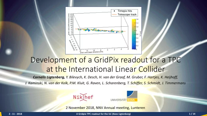
Development of a GridPix readout for a TPC at the International Linear Collider
Cornelis Ligtenberg, Y. Bilevych, K. Desch, H. van der Graaf, M. Gruber, F. Hartjes, K. Heijhoff,
- J. Kaminski, N. van der Kolk, P.M. Kluit, G. Raven, L. Scharenberg, T. Schiffer, S. Schmidt, J. Timmermans
2 November 2018, NNV Annual meeting, Lunteren
2 - 11 - 2018 A Gridpix TPC readout for the ILC (Kees Ligtenberg)