
4/13/2010 1
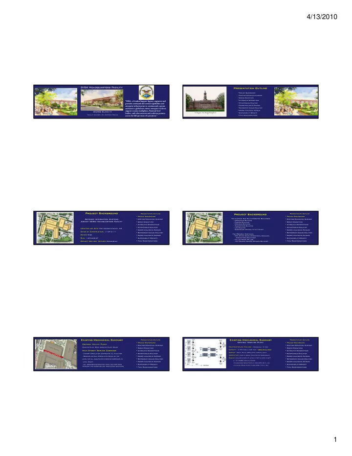
DI DISA He Headquarters F Facility ty
George S Slavik ik III III
Faculty Advisor: Dr. Stephen Treado
“DISA, a Combat Support Agency, engineers and provides command and control capabilities and enterprise infrastructure to continuously operate and assure a global net-centric enterprise in direct support to joint warfighters, National level leaders, and other mission and coalition partners across the full spectrum of operations.”
Pr Presen entati tion Outlin Outline
- Pr
- Proj
- ject Ba
Back ckground
- E
Existing Mechan anic ical al Summar ary
- D
- Desi
sign Object ctives
- A
- Alte
ternative Descr scriptions
- Wate
ter C Cool
- oled S
Solution
- Energy An
Anal alysis & & Payb yback
- Refrigerant C
Cool
- oled S
Solution
- Energy An
Anal alysis & & Payb yback
- S
- Sust
stainability Br Breadth
- F
Final l Re Recommendations
Project B t Background
- und
Defense Information Systems Agency (DISA) Headquarters Facility Location and Site: Fort George G Meade , MD Dates of Construction: 1/1/09-2/1/11 Owner: DISA Size: 1,070,000 SF Project Delivery Method: Design-Build
Presentation Outline
- P
- Project Ba
Background
- Existin
ting M Mechanic ical S Summa mmary
- D
- Design Objectives
- Al
- Alte
ternative Descriptions
- Water
ter C Cooled ed S Solutio tion
- Energy A
Analysi ysis & & Payba yback
- R
Refrig iger erant Cooled ed Solutio tion
- Energy A
Analysi ysis & & Payba yback
- S
- Sustainability Br
Brea eadth
- Fi
Fina nal l Re Recommenda ndations ns
Project B t Background
- und
The Campus Has Six Integrated Buildings:
- Operations Building
- Common Building
- Command Building
- Acquisitions Building
- Lab Building
- Warehouse/ Central Utility Plant
The Program Contains:
- 70% Office Space (Operations, Command,
Acquisitions Buildings)
- 7% Lab Space (TE Lab)
- 10% Common Spaces (Common Building)
Presentation Outline
- P
- Project Ba
Background
- Existin
ting M Mechanic ical S Summa mmary
- D
- Design Objectives
- Al
- Alte
ternative Descriptions
- Water
ter C Cooled ed S Solutio tion
- Energy A
Analysi ysis & & Payba yback
- R
Refrig iger erant Cooled ed Solutio tion
- Energy A
Analysi ysis & & Payba yback
- S
- Sustainability Br
Brea eadth
- Fi
Fina nal l Re Recommenda ndations ns
Existing M ting Mechanic anical S al Summary
Central Utility Plant
Heating Plant (Red), Cooling Plant (Blue)
Main Street Service Corridor
- 2 story Circulation connecting all buildings
- Doubles as Main Circulation Spine on top
level for all occupants & Service Corridor on level below.
- All CHW/HW Distribution from the CUP runs
through this corridor and feds other buildings Presentation Outline
- P
- Project Ba
Background
- Existin
ting M Mechanic ical S Summa mmary
- D
- Design Objectives
- Al
- Alte
ternative Descriptions
- Water
ter C Cooled ed S Solutio tion
- Energy A
Analysi ysis & & Payba yback
- R
Refrig iger erant Cooled ed Solutio tion
- Energy A
Analysi ysis & & Payba yback
- S
- Sustainability Br
Brea eadth
- Fi
Fina nal l Re Recommenda ndations ns Four Centrifugal Chillers – Refrigerant R-134A Capacity – 2- 975 Tons, 2- 925 Tons = 3800 Total Tons Serves – AHU’s, FCU’s, CRAC Units, Terminal Units Orientation- Piped in Series/ Counterflow Arrangement Design- Chillers operate W. Chws at 42°F & Chwr at 60°F 4- 13,125MBH Cooling Towers 5- Condenser Water Pumps (1,750 GPM, 90 ft. wc.) 5- Chilled Water Pumps (1,265 GPM, 175 ft. Wc.)
Central Cooling Plant
Existing M ting Mechanic anical S al Summary
Presentation Outline
- P
- Project Ba
Background
- Existin
ting M Mechanic ical S Summa mmary
- D
- Design Objectives
- Al
- Alte
ternative Descriptions
- Water
ter C Cooled ed S Solutio tion
- Energy A
Analysi ysis & & Payba yback
- R
Refrig iger erant Cooled ed Solutio tion
- Energy A
Analysi ysis & & Payba yback
- S
- Sustainability Br
Brea eadth
- Fi
Fina nal l Re Recommenda ndations ns