
SLIDE 1
10/20/08 1 P561: Network Systems Week 4: Internetworking II
Tom Anderson Ratul Mahajan TA: Colin Dixon
Today
Internet routing (BGP) Tunneling and MPLS Wireless routing Wireless handoffs
2
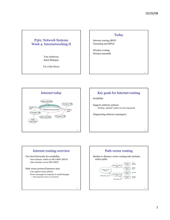
Internet today
3
Key goals for Internet routing
Scalability Support arbitrary policies
- Finding “optimal” paths was less important
(Supporting arbitrary topologies)
4
Internet routing overview
Two-level hierarchy for scalability
- Intra-domain: within an ISP (OSPF, MPLS)
- Inter-domain: across ISPs (BGP)
Path vector protocol between Ases
- Can support many policies
- Fewer messages in response to small changes
- Only impacted routers are informed
5
Path vector routing
Similar to distance vector routing info includes entire paths
6
192.4.23, [7] 192.4.23, [3, 7]