
SLIDE 1
1
Modelling
- The creation and manipulation of a system representation is
termed modelling
- Any single representation is called a model of the system.
- There are mainly two kinds (conventional):
- Descriptive (e.g. a set of equations or rules to define parameter
relationships)
- Graphical/volumetric (e.g. architectural and engineering system).
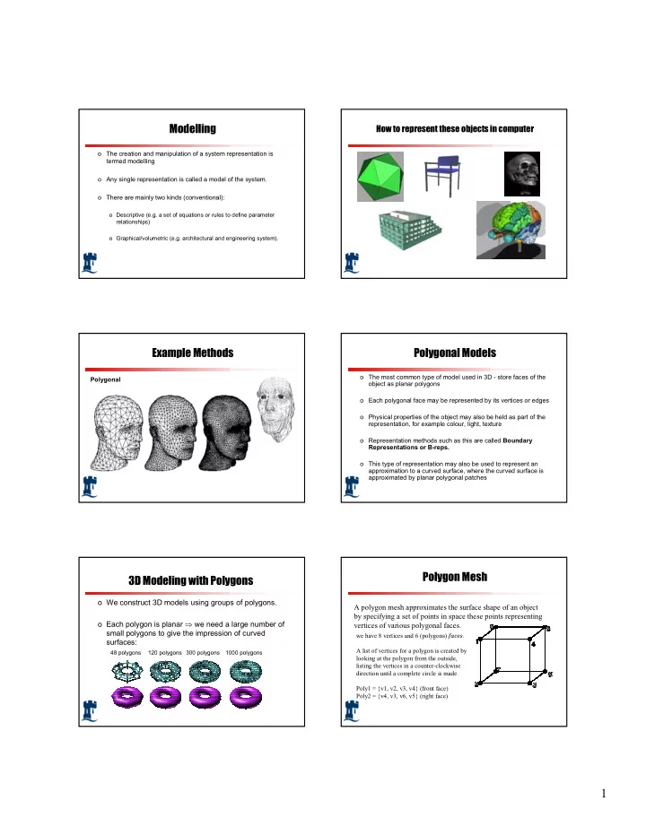
How to represent these objects in computer
Example Methods
Polygonal
Polygonal Models
- The most common type of model used in 3D - store faces of the
- bject as planar polygons
- Each polygonal face may be represented by its vertices or edges
- Physical properties of the object may also be held as part of the
representation, for example colour, light, texture
- Representation methods such as this are called Boundary
Representations or B-reps.
- This type of representation may also be used to represent an
approximation to a curved surface, where the curved surface is approximated by planar polygonal patches
3D Modeling with Polygons
- We construct 3D models using groups of polygons.
- Each polygon is planar ⇒ we need a large number of