1
play

1 Memory Read Transaction (1) Memory Read Transaction (2) CPU - PDF document

Today Storage technologies and trends Locality of reference The Memory Hierarchy Caching in the memory hierarchy CSci 2021: Machine Architecture and Organization March 30th-April 1st, 2020 Your instructor: Stephen McCamant Based on


  1. Today  Storage technologies and trends  Locality of reference The Memory Hierarchy  Caching in the memory hierarchy CSci 2021: Machine Architecture and Organization March 30th-April 1st, 2020 Your instructor: Stephen McCamant Based on slides originally by: Randy Bryant, Dave O’Hallaron 1 2 Bryant and O’Hallaron, Computer Systems: A Programmer’s Perspective, Third Edition Bryant and O’Hallaron, Computer Systems: A Programmer’s Perspective, Third Edition Random-Access Memory (RAM) SRAM vs DRAM Summary  Key features  RAM is traditionally packaged as a chip.  Basic storage unit is normally a cell (one bit per cell). Trans. Access Needs Needs  Multiple RAM chips form a memory. per bit time refresh? EDC? Cost Applications SRAM 4 or 6 1X No Maybe 100x Cache memories  RAM comes in two varieties:  SRAM (Static RAM) DRAM 1 10X Yes Yes 1X Main memories,  DRAM (Dynamic RAM) frame buffers 3 4 Bryant and O’Hallaron, Computer Systems: A Programmer’s Perspective, Third Edition Bryant and O’Hallaron, Computer Systems: A Programmer’s Perspective, Third Edition Traditional Bus Structure Connecting Nonvolatile Memories CPU and Memory  DRAM and SRAM are volatile memories  A bus is a collection of parallel wires that carry address,  Lose information if powered off. data, and control signals.  Nonvolatile memories retain value even if powered off  Buses are typically shared by multiple devices.  Read-only memory (ROM): programmed during production  Programmable ROM (PROM): can be programmed once  Eraseable PROM (EPROM): can be bulk erased (UV, X-Ray) CPU chip  Electrically eraseable PROM (EEPROM): electronic erase capability Register file  Flash memory: EEPROMs. with partial (block-level) erase capability  Wears out after about 100,000 erasings ALU  Uses for Nonvolatile Memories System bus Memory bus  Firmware programs stored in a ROM (BIOS, controllers for disks, network cards, graphics accelerators, security subsystems,…)  Solid state disks (replace rotating disks in thumb drives, smart Main I/O Bus interface phones, mp3 players, tablets, laptops,…) bridge memory  Disk caches 5 6 Bryant and O’Hallaron, Computer Systems: A Programmer’s Perspective, Third Edition
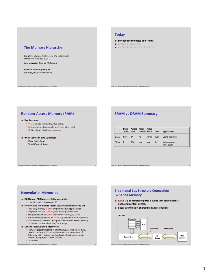
 Bryant and O’Hallaron, Computer Systems: A Programmer’s Perspective, Third Edition 1

  2. Memory Read Transaction (1) Memory Read Transaction (2)  CPU places address A on the memory bus.  Main memory reads A from the memory bus, retrieves word x, and places it on the bus. Register file Register file Load operation: movq A, %rax Load operation: movq A, %rax ALU ALU %rax %rax Main memory Main memory I/O bridge 0 I/O bridge 0 x A Bus interface Bus interface x A x A 7 8 Bryant and O’Hallaron, Computer Systems: A Programmer’s Perspective, Third Edition Bryant and O’Hallaron, Computer Systems: A Programmer’s Perspective, Third Edition Memory Read Transaction (3) Memory Write Transaction (1)  CPU read word x from the bus and copies it into register CPU places address A on bus. Main memory reads it and  %rax. waits for the corresponding data word to arrive. Register file Register file Load operation: movq A, %rax Store operation: movq %rax, A ALU ALU %rax %rax x y Main memory Main memory 0 0 I/O bridge I/O bridge A Bus interface Bus interface A A x 9 10 Bryant and O’Hallaron, Computer Systems: A Programmer’s Perspective, Third Edition Bryant and O’Hallaron, Computer Systems: A Programmer’s Perspective, Third Edition Memory Write Transaction (2) Memory Write Transaction (3) CPU places data word y on the bus. Main memory reads data word y from the bus and stores   it at address A. Register file Register file Store operation: movq %rax, A Store operation: movq %rax, A ALU ALU %rax %rax y y main memory Main memory 0 0 I/O bridge I/O bridge y Bus interface Bus interface y A A 11 12 Bryant and O’Hallaron, Computer Systems: A Programmer’s Perspective, Third Edition Bryant and O’Hallaron, Computer Systems: A Programmer’s Perspective, Third Edition 2

  3. What’s Inside A Disk Drive? Disk Geometry Spindle Arm  Disks consist of platters, each with two surfaces. Platters  Each surface consists of concentric rings called tracks.  Each track consists of sectors separated by gaps. Actuator Tracks Surface Track k Gaps Electronics (including a Spindle processor SCSI and memory!) connector Image courtesy of Seagate Technology Sectors 14 15 Bryant and O’Hallaron, Computer Systems: A Programmer’s Perspective, Third Edition Bryant and O’Hallaron, Computer Systems: A Programmer’s Perspective, Third Edition Disk Geometry (Muliple-Platter View) Disk Capacity Aligned tracks form a cylinder.  Capacity: maximum number of bits that can be stored.   Vendors express capacity in units of gigabytes (GB), where Cylinder k 1 GB = 10 9 Bytes.  Capacity is determined by these technology factors: Surface 0 Platter 0 Surface 1  Recording density (bits/in): number of bits that can be squeezed Surface 2 into a 1 inch segment of a track. Platter 1 Surface 3  Track density (tracks/in): number of tracks that can be squeezed Surface 4 Platter 2 into a 1 inch radial segment. Surface 5  Areal density (bits/in2): product of recording and track density. Spindle 16 17 Bryant and O’Hallaron, Computer Systems: A Programmer’s Perspective, Third Edition Bryant and O’Hallaron, Computer Systems: A Programmer’s Perspective, Third Edition Recording zones Computing Disk Capacity  Modern disks partition tracks Capacity = (# bytes/sector) x (avg. # sectors/track) x into disjoint subsets called (# tracks/surface) x (# surfaces/platter) x recording zones (# platters/disk) …  Each track in a zone has the same Example:  512 bytes/sector number of sectors, determined  300 sectors/track (on average) by the circumference of innermost track. Spindle  20,000 tracks/surface  Each zone has a different number  2 surfaces/platter of sectors/track, outer zones  5 platters/disk have more sectors/track than inner zones. Capacity = 512 x 300 x 20000 x 2 x 5  So we use average number of = 30,720,000,000 sectors/track when computing = 30.72 GB capacity. 18 19 Bryant and O’Hallaron, Computer Systems: A Programmer’s Perspective, Third Edition Bryant and O’Hallaron, Computer Systems: A Programmer’s Perspective, Third Edition 3

  4. Disk Operation (Single-Platter View) Disk Operation (Multi-Platter View) Read/write heads move in unison The disk surface The read/write head from cylinder to cylinder spins at a fixed is attached to the end rotational rate of the arm and flies over the disk surface on a thin cushion of air. Arm spindle spindle spindle spindle spindle Spindle By moving radially, the arm can position the read/write head over any track. 20 21 Bryant and O’Hallaron, Computer Systems: A Programmer’s Perspective, Third Edition Bryant and O’Hallaron, Computer Systems: A Programmer’s Perspective, Third Edition Disk Structure - top view of single platter Disk Access Surface organized into tracks Tracks divided into sectors Head in position above a track 22 23 Bryant and O’Hallaron, Computer Systems: A Programmer’s Perspective, Third Edition Bryant and O’Hallaron, Computer Systems: A Programmer’s Perspective, Third Edition Disk Access Disk Access – Read Rotation is counter-clockwise About to read blue sector 24 25 Bryant and O’Hallaron, Computer Systems: A Programmer’s Perspective, Third Edition Bryant and O’Hallaron, Computer Systems: A Programmer’s Perspective, Third Edition 4

  5. Disk Access – Read Disk Access – Read After BLUE read After BLUE read After reading blue sector Red request scheduled next 26 27 Bryant and O’Hallaron, Computer Systems: A Programmer’s Perspective, Third Edition Bryant and O’Hallaron, Computer Systems: A Programmer’s Perspective, Third Edition Disk Access – Seek Disk Access – Rotational Latency After BLUE read Seek for RED After BLUE read Seek for RED Rotational latency Seek to red’s track Wait for red sector to rotate around 28 29 Bryant and O’Hallaron, Computer Systems: A Programmer’s Perspective, Third Edition Bryant and O’Hallaron, Computer Systems: A Programmer’s Perspective, Third Edition Disk Access – Read Disk Access – Service Time Components After BLUE read Seek for RED Rotational latency After RED read After BLUE read Seek for RED Rotational latency After RED read Complete read of red Data transfer Seek Rotational Data transfer latency 30 31 Bryant and O’Hallaron, Computer Systems: A Programmer’s Perspective, Third Edition Bryant and O’Hallaron, Computer Systems: A Programmer’s Perspective, Third Edition 5

Download Presentation
Download Policy: The content available on the website is offered to you 'AS IS' for your personal information and use only. It cannot be commercialized, licensed, or distributed on other websites without prior consent from the author. To download a presentation, simply click this link. If you encounter any difficulties during the download process, it's possible that the publisher has removed the file from their server.

Recommend


More recommend