
1
June 7, 2005
Massachusetts Institute of Technology
Factored Symbolic Approach to Reactive Planning
Seung H. Chung Brian C. Williams
2
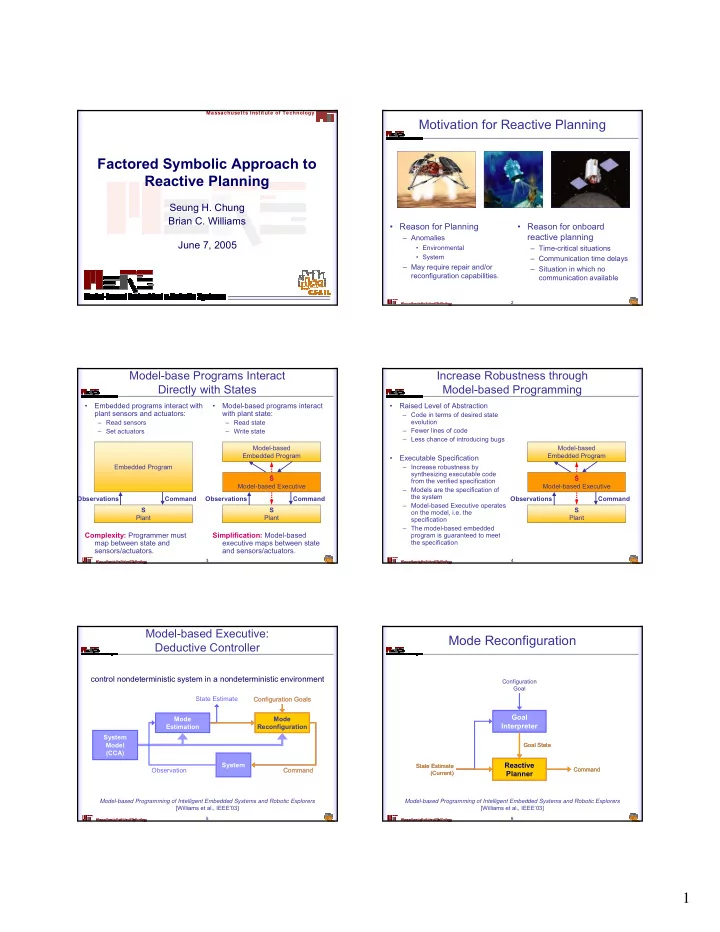
Motivation for Reactive Planning
- Reason for Planning
– Anomalies
- Environmental
- System
– May require repair and/or reconfiguration capabilities.
- Reason for onboard
reactive planning
– Time-critical situations – Communication time delays – Situation in which no communication available
3
Model-base Programs Interact Directly with States
- Embedded programs interact with
plant sensors and actuators:
– Read sensors – Set actuators
Complexity: Programmer must map between state and sensors/actuators.
- Model-based programs interact
with plant state:
– Read state – Write state
Simplification: Model-based executive maps between state and sensors/actuators.
Embedded Program S Plant Observations Command Model-based Embedded Program S Plant Observations Command Ŝ Model-based Executive
4
Increase Robustness through Model-based Programming
- Raised Level of Abstraction
– Code in terms of desired state evolution – Fewer lines of code – Less chance of introducing bugs
- Executable Specification
– Increase robustness by synthesizing executable code from the verified specification – Models are the specification of the system – Model-based Executive operates
- n the model, i.e. the
specification – The model-based embedded program is guaranteed to meet the specification Model-based Embedded Program S Plant Observations Command Ŝ Model-based Executive
5
Model-based Executive: Deductive Controller
Model-based Programming of Intelligent Embedded Systems and Robotic Explorers [Williams et al., IEEE’03]
Mode Estimation Command Configuration Goals Observation Mode Reconfiguration State Estimate System Model (CCA) System Mode Reconfiguration Command Configuration Goals
control nondeterministic system in a nondeterministic environment
6
Mode Reconfiguration
Model-based Programming of Intelligent Embedded Systems and Robotic Explorers [Williams et al., IEEE’03]
Goal Interpreter Reactive Planner
Configuration Goal Command Goal State State Estimate (Current)
Reactive Planner
Command Goal State State Estimate (Current)