yarns and sheets from well allined multi walled carbon
play

YARNS AND SHEETS FROM WELL ALLINED MULTI-WALLED CARBON NANOTUBES - PDF document

18 TH INTERNATIONAL CONFERENCE ON COMPOSITE MATERIALS YARNS AND SHEETS FROM WELL ALLINED MULTI-WALLED CARBON NANOTUBES H.S. Jang 1 , S.C. Lee 2 , C.S. Kim 2 , S.H. Nahm 1 * 1 Center for Materials Measurement, Korea Research Institute of Standards


  1. 18 TH INTERNATIONAL CONFERENCE ON COMPOSITE MATERIALS YARNS AND SHEETS FROM WELL ALLINED MULTI-WALLED CARBON NANOTUBES H.S. Jang 1 , S.C. Lee 2 , C.S. Kim 2 , S.H. Nahm 1 * 1 Center for Materials Measurement, Korea Research Institute of Standards and Science, Daejeon, 305-340, Korea 2 Department of IT Convergence & Application Engineering, Pukyong National University, Pusan 608-739, Korea * Corresponding author(shnahm@kriss.re.kr) Keywords : spinning, carbon nanotubes, yarn, sheet 1 Introduction iron films were inserted into the CVD chamber and Carbon nanotubes (CNTs) have been attended to use ramped to the set point temperature of 800 ˚C at a extensively as components in various nano/micro- ramping rate of 50 ˚C while flowing Ar (400 sccm) system due to their unique physical and chemical and H 2 (20 sccm). The growth of MWCNTs was properties. The growth technique of CNTs have performed at the same temperature and pressure of been developed for suitable their application. In about 21 Torr by C 2 H 2 gas (100 sccm) to the flow particular, Jiang et al. grew multi-walled CNT for 30 min. The grown MWCNTs on the substrate (MWCNT) forests that were well-aligned arrays and was shown in Fig. 1a) and Fig. 1b) shows the high pulled a yarn from them [1]. Zhang et al. produced resolution scanning electron microscopy (SEM) transparent conductive MWCNT sheets simply by image of the grown MWCNTs. The MWCNTs spinning MWCNTs [2]. In addition, MWCNT sheet grown on the substrate were ~12 nm of diameter, the films can be produced simply by being continuously height of MWCNT forests was 250~300 μm. drawn out from super-aligned MWCNTs on the a) substrate. The sheet films were expected to be 
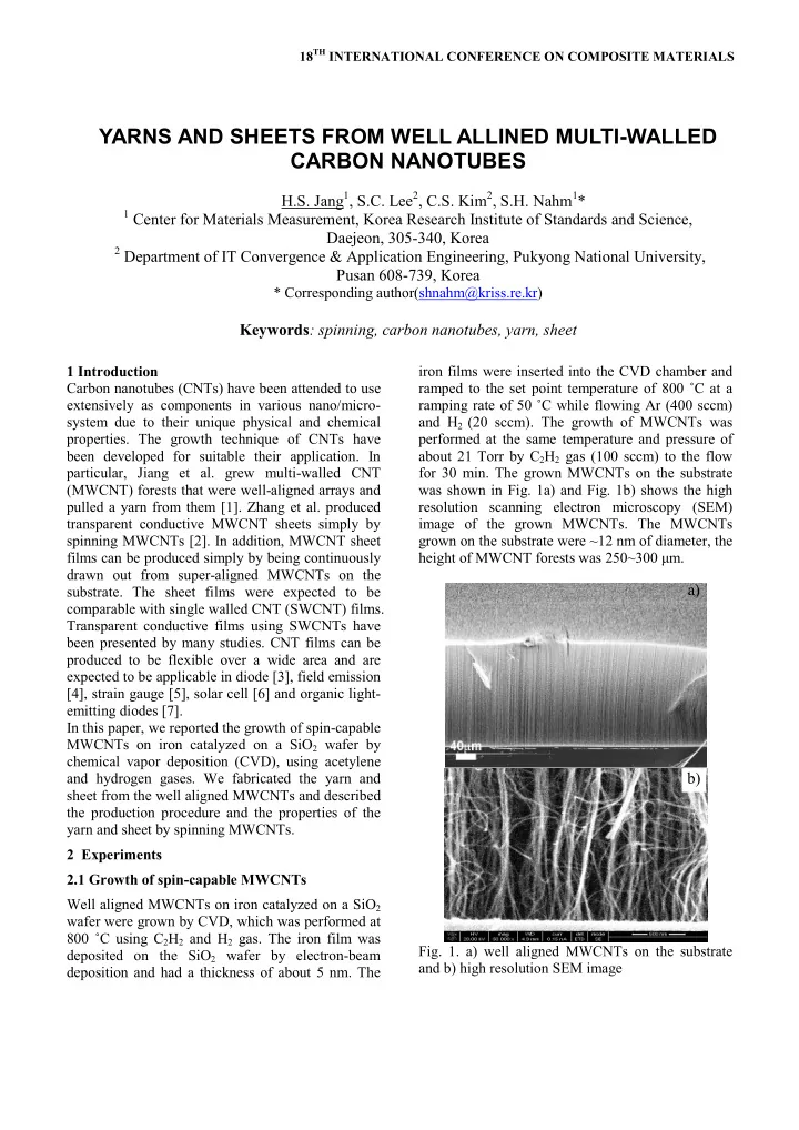
comparable with single walled CNT (SWCNT) films. Transparent conductive films using SWCNTs have been presented by many studies. CNT films can be produced to be flexible over a wide area and are expected to be applicable in diode [3], field emission [4], strain gauge [5], solar cell [6] and organic light- emitting diodes [7]. In this paper, we reported the growth of spin-capable MWCNTs on iron catalyzed on a SiO 2 wafer by chemical vapor deposition (CVD), using acetylene b) and hydrogen gases. We fabricated the yarn and sheet from the well aligned MWCNTs and described the production procedure and the properties of the yarn and sheet by spinning MWCNTs. 2 Experiments 2.1 Growth of spin-capable MWCNTs Well aligned MWCNTs on iron catalyzed on a SiO 2 wafer were grown by CVD, which was performed at 800 ˚C using C 2 H 2 and H 2 gas. The iron film was Fig. 1. a) well aligned MWCNTs on the substrate deposited on the SiO 2 wafer by electron-beam and b) high resolution SEM image deposition and had a thickness of about 5 nm. The

  2. The growth of MWCNTs on the substrate was also b) a) performed when the thickness of Fe film were about 3 and 7 nm, respectively. MWCNTs were well grown on both films, as shown in Fig . Unfortunately, both samples were not able to continually spun MWCNTs. The growth for spinning MWCNTs was strongly depended on the c) thickness of Fe film. We compared the areal density of MWCNTs grown on the substrates in order to more fully understand Fig. 3. SEM images of a) yarn from the grown how ith is related to: the spinning capability of the MWCNTs and b) high resolution of MWCNT yarns. forest, the alignment of the MWCNTs in the forest. c) photo shows the MWCNT yarns Spin-capable forests resulting from Fe film have high areal density of (~1.8±5) ´ 10 10 tubes/cm 2 . The a) b) MWCNTs grown on 30 nm and 70 nm of film thickness have the areal density of ~8.7 ´ 10 9 and 1.4 ´ 10 10 tubes/cm 2 , respectively. The MWCNTs grown on 30 nm and 70 nm of film thickness has lower areal density then the MWCNTs grown on 50 nm of film thickness. When the MWCNTs areal density is low, the MWCNT forests are generally curled or wavy because neighboring tubes are not close enough to have strong Van der Waals c) d) interactions between tubes as shown in Fig. 2b) and d). As compared Fig. 1b), Fig. 2b) and d) shows the low density and the declined alignment of MWCNTs. a) b) Fig. 4. SEM images shows a) top and b) side view of sheets produced from the well aligned MWCNTs. c) photo and d) SEM image of sheet films. This suggests that the high areal density promotes alignment of the MWCNTs, perhaps through Van der Waals interactions between growing MWCNTs c) d) [9]. 2.2 Manufacture of yarn and sheet As shown in Fig. 3a) the micron-sized MWCNT yarns were produced by twisting MWCNTs. Fig. 3b) shows the SEM image of MWCNT yarns. As shown in Fig. 3c), the photo image shows the MWCNT yarns. The MWCNT sheets were produced by being Fig. 2. a) SEM image and b) high resolution image continuously pulled out from the grown MWCNTs, of the MWCNTs grown on the Fe film of 30 nm. c) as shown in Fig. 4a). Fig. 4b) shows the side view of SEM image and d) high resolution image of the the sheets from the grown MWCNTs on the substate. MWCNTs grown on the Fe film of 70 nm. The MWCNT sheet films were produced by directly coating MWCNT sheets on a poly ethylen

  3. PAPER TITLE terephthalate (PET). Alcohol was sprayed over the whole surface of MWCNT sheets, which was then dried at 80 °C for 1 h in an oven. Al foils were then put into contact on both ends of MWCNT sheet with a silver paste. The PET film was also coated on top of MWCNT sheets coated on the PET film. The MWCNT sheets prepared MWCNT sheet films are shown in Fig. 4c). The SEM image shows the top region of the sheets, as shown in Fig. 4d). 2.3 Electric characterization of yarn and sheet The MWCNT yarns was immersed in water and the electric resistance of yarn was measured while raising the temperature from 23 °C to boiling point of water as shown in Fig 3. The diameter of yarn is Fig. 6. AFM images of sheets on the substrate. about 100 μm. Black and red allows in Fig. 5 indicated 23 °C and boiling point of water, The morphology of the MWCNT sheets was respectively. characterized by atomic force microscope (AFM). The electric resistance was linearly decreased to The voltage source (Agilent E3634A) was directly boiling point of water. The electric resistance was connected to both ends of the Al foil electrode on depended on the temperature of water. An intuitive the sheet films, and the current and resistance of the approach to temperature dependence leads one to sheet films were measured with a digital multimeter expect change in resistance which is proportional to (Agilent 34401A). MWCNT sheet films were the temperature change: fabricated with a uniform density of ~1.8±5 ´ 10 10 R=R 0 [1+α(T-T 0 )] , tubes/cm 2 , sheet resistances of ~699 Ω/sq, and where R is the current resistance, R 0 is initial transmittances of 81% to 85% [8]. resistance, α is temperature coefficient, T is current The AFM images of sheet films are shown in Fig. 6. temperature and T 0 is initial temperature. The The thicknesses of the MWCNT sheets were temperature coefficient of MWCNT yarns was obtained by measuring the heights measured via calculated to ( - 1.2 ± 0.3) ´ 10 -3 /°C. We expect that AFM. The thickness of the sheet was under 100 nm yarn can be applied to temperature sensor. (Fig. 6), The prepared MWCNT sheet films were heated by supplying DC power. The size of sheet film is 1.15 ´ 0.7 cm 2 . The surface temperature of the single sheet films were measured using the infrared thermal camera while a DC voltage was supplied. The defroster in the window of vehicles requires 12 V of driving voltage. The current value of the sheet film was measured to 15.8 mA. The sheet film reached temperature of 56 to 58 °C at an applied voltage of 12 V. The sheet film required ~0.189 W of DC power to increase the sheet temperature to ~58 °C. We propose that the MWCNT sheet films have less sheet resistance and/or electrical resistance spread over the same area as compared to car windows. We measured the temperature of the heat film at an Fig. 5. The electrical resistance variation was applied voltage of 12 V from outside of - 3 °C. As depended on the temperature change of water shown in Fig. 7, the film heater was comparable with a car window. 3

Download Presentation
Download Policy: The content available on the website is offered to you 'AS IS' for your personal information and use only. It cannot be commercialized, licensed, or distributed on other websites without prior consent from the author. To download a presentation, simply click this link. If you encounter any difficulties during the download process, it's possible that the publisher has removed the file from their server.

Recommend


More recommend