
SLIDE 1
Fermilab
- Dr. O’Sheg Oshinowo
IWAA2012 Conference Fermilab, Batavia, IL, USA September 10-14, 2012
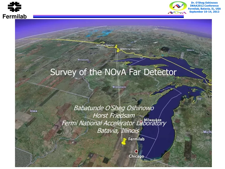
The NO n A Experiment Survey of the NOvA Far Detector Babatunde - - PowerPoint PPT Presentation
Dr. OSheg Oshinowo IWAA2012 Conference Fermilab, Batavia, IL, USA September 10-14, 2012 Fermilab The NO n A Experiment Survey of the NOvA Far Detector Babatunde OSheg Oshinowo Horst Friedsam Gary Feldman Fermi National Accelerator
IWAA2012 Conference Fermilab, Batavia, IL, USA September 10-14, 2012
IWAA2012 Conference Fermilab, Batavia, IL, USA September 10-14, 2012
IWAA2012 Conference Fermilab, Batavia, IL, USA September 10-14, 2012
Ash River
Minneapolis Duluth International Falls Fermilab
Ash River
Minneapolis Duluth International Falls Fermilab
IWAA2012 Conference Fermilab, Batavia, IL, USA September 10-14, 2012
IWAA2012 Conference Fermilab, Batavia, IL, USA September 10-14, 2012
IWAA2012 Conference Fermilab, Batavia, IL, USA September 10-14, 2012
IWAA2012 Conference Fermilab, Batavia, IL, USA September 10-14, 2012
15.6 m 15.6 m
IWAA2012 Conference Fermilab, Batavia, IL, USA September 10-14, 2012
IWAA2012 Conference Fermilab, Batavia, IL, USA September 10-14, 2012
Pivoter Rails Book End
IWAA2012 Conference Fermilab, Batavia, IL, USA September 10-14, 2012
IWAA2012 Conference Fermilab, Batavia, IL, USA September 10-14, 2012
IWAA2012 Conference Fermilab, Batavia, IL, USA September 10-14, 2012
IWAA2012 Conference Fermilab, Batavia, IL, USA September 10-14, 2012
Pivoter Rails Book End
IWAA2012 Conference Fermilab, Batavia, IL, USA September 10-14, 2012
IWAA2012 Conference Fermilab, Batavia, IL, USA September 10-14, 2012 Ash River
IWAA2012 Conference Fermilab, Batavia, IL, USA September 10-14, 2012
in the Far Detector building for positioning the Far Detector using the API Laser Tracker
Leica AT401
and 36 wall monuments in the Far Detector Hall and the Detector assembly area. Secondary network consists of 44 wall monuments
surface network using the Geodimeter Total Station
Floor Monument
Upper Level Lower Level Surface Network
IWAA2012 Conference Fermilab, Batavia, IL, USA September 10-14, 2012
IWAA2012 Conference Fermilab, Batavia, IL, USA September 10-14, 2012
Tracker
End was reported to use for possible adjustments Pivoter Rail Plane
IWAA2012 Conference Fermilab, Batavia, IL, USA September 10-14, 2012
IWAA2012 Conference Fermilab, Batavia, IL, USA September 10-14, 2012
measured with the Trimble S6 Total Station using 24” x 24” (61 cm x 61 cm) grids
with the Table in the vertical position
IWAA2012 Conference Fermilab, Batavia, IL, USA September 10-14, 2012
IWAA2012 Conference Fermilab, Batavia, IL, USA September 10-14, 2012
measured with the Laser Tracker using 24” x 24” (61 cm x 61 cm) grids
with the Table in the horizontal position
surface was shimmed accordingly and covered with plywood
IWAA2012 Conference Fermilab, Batavia, IL, USA September 10-14, 2012
IWAA2012 Conference Fermilab, Batavia, IL, USA September 10-14, 2012
IWAA2012 Conference Fermilab, Batavia, IL, USA September 10-14, 2012
IWAA2012 Conference Fermilab, Batavia, IL, USA September 10-14, 2012