
SLIDE 1
| PAGE 1
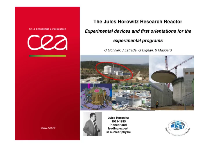
The Jules Horowitz Research Reactor
Experimental devices and first orientations for the experimental programs
C Gonnier, J Estrade, G Bignan, B Maugard
Jules Horowitz 1921-1995 Pioneer and leading expert in nuclear physic
The Jules Horowitz Research Reactor Experimental devices and first - - PowerPoint PPT Presentation
The Jules Horowitz Research Reactor Experimental devices and first orientations for the experimental programs C Gonnier, J Estrade, G Bignan, B Maugard Jules Horowitz 1921-1995 Pioneer and leading expert in nuclear physic | PAGE 1 Jules
| PAGE 1
Jules Horowitz 1921-1995 Pioneer and leading expert in nuclear physic
9 NOVEMBRE 2017Q& | PAGE 2
'
HBWR OSIRIS BR 2
under construction
HFR LVR 15 RJH
OSIRIS
Generation 3 Existing fleet 40-year plant life
Generation 3
Plant life extension beyond 40 years
Generation 4
Safety and Plant life time management (ageing & new plants) Fuel behaviour validation in incidental and accidental situation Assess innovations and related safety for future NPP: Gen 3 and Gen 4 Training of new generations
Existing technologies PWR, BWR, …
Illustration
power evolution in France
See the presentation dedicated to the Moly production in JHR
| PAGE 3
60 cm
Hot cells (non destructive examinations) Reactor pool with examination benches Core (Φ Φ Φ Φ 70cm / h 60 cm) and Be reflector Storage pools Reactor block JHR fuel element
Water channels in Be reflector
Experimental cubicles and analysis laboratories
BR : Φ 37m H 45m BAN : 51x47m H 35m Pool : Φ 7m H 12m
Core Designed for UMo-Al fuel Start-up with U3Si2-Al fuel 70 MWth / 100 MWth 25 to 30 days cycle length 6-7 days shutdown Rooms dedicated to reactor operation
(heat exchangers, primary pumps, safety systems,…)
Rooms dedicated to reactor operation
(control room, hot workshop, labs,…)
About 200 aseismic pads
| PAGE 4
Thermal neutron flux Fast neutron flux
| PAGE 5
LINAC (X) γ γ γ γ-detector Shielding XR-detector Tunable γ
γ γ γ front collimator
Device
Side cutaway
Pool bank fixing Penetration X-table Y-table Bench Z-table XR-collimator
View from the core
9 NOVEMBRE 2017 | PAGE 6
reference possible evolution
Power transient (up to 620W/cm), post clad failure fuel behavior, Lift-off experiment…
Ballooning and clad burst (fuel relocation) Corrosion at high temperature Quenching and post- quench behaviour
Fuel µstructure Clad corrosion
9 NOVEMBRE 2017 | PAGE 7
tensile tests, resilience test (Charpy), crack propagation tests …..
(Water loop, 190 bar, 360°C, radiolysis, representative chemical conditions, samples under stress …) .
specimen for µ structure evolution, tensile test ; for 1 or 2 D creep tests ; for bending tests (stress releiving experiments) ;…
Equivalent carrying volume 30x62.5x500mm3 Helium 230 – 300°C 100 mdpa/year
| PAGE 8
Thermo-Mechanical Fatigue testing: study of components submitted to both mechanical strain and
Ceramic testing (for diagnostic windows); samples bi-axially loaded, analysis of optical properties and
Cryogenic testing for the study of electrical and structural properties of superconducting magnet
Thermo- mechanical fatigue Ceramic testing Cryogenic testing
Material irradiation : adaptation for high temperature, up to 650°C Fuel irradiation : In-core : long term irradiations (NaK- neutron filters)
| PAGE 10
Measurement of Fission Gas Release By using an acoustic sensor Measurement technics using optical fibers On-line Measurement of Fast neutron flux in MTRs Sub-miniature fission chambers
July 2007 September 2009 December 2010
July 2011 containment wall first pouring November 2012 December 2013 January 2015
2015
19/03/2007 Signature of the JHR consortium Mid 2017
Polar crane testing nov 2014 Emergency diesel generator (tested on a shacking table)
Primary pump testing
Mock up of displacement system Currently under testing Manufacturing of core components Heat exchangers (primary/secondary system)
Double envelop tight connector (patented) “Two-way Filter” (patented), dedicated to trap Na-K
Test device heads Cables and pipes connection Heaters qualification Qualification of sensors under irradiation Sample holder handling in hot cells CLOE : feedthroughs, flow amplifier, chemistry control ; sample holder, loading system, DCPD,… Lorelei 900°C Mica
Occitane
| PAGE 15
Temperature distribution in the test section
IAEC
9 NOVEMBRE 2017 | PAGE 17
See the presentation dedicated to the FIJHOP R&D program proposal
9 NOVEMBRE 2017 | PAGE 18
9 NOVEMBRE 2017 | PAGE 19
9 NOVEMBRE 2017 | PAGE 20
See the presentation dedicated to the FIJHOP R&D program proposal
9 NOVEMBRE 2017 | PAGE 21 CEA | 10 AVRIL 2012