
SLIDE 1
Dos Rios WRC
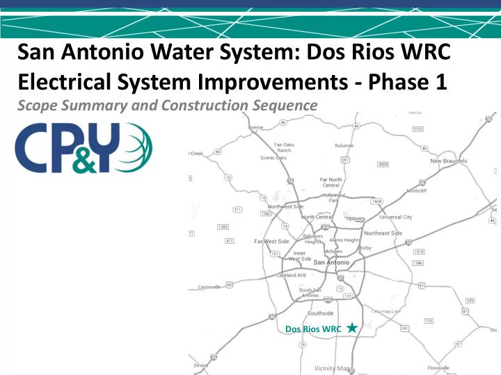
Scope Summary and Construction Sequence
San Antonio Water System: Dos Rios WRC Electrical System Improvements - Phase 1
Vicinity Map
San Antonio Water System: Dos Rios WRC Electrical System - - PowerPoint PPT Presentation
San Antonio Water System: Dos Rios WRC Electrical System Improvements - Phase 1 Scope Summary and Construction Sequence Dos Rios WRC Vicinity Map DOS RIOS WRC Presentation Outline Table of Contents Scope Summary 1. Special Constraints 2.
Dos Rios WRC
Vicinity Map
1.
Contractor shall field verify, investigate, and confirm all affected underground utilities prior to beginning construction.
2.
Relocation of Large Utility Lines prior to beginning construction of proposed improvements.
3.
Incoming pole utility work shall not be performed until new infrastructure is in place.
4.
Demolition of Substations 11 & 12 shall not occur until the new installation and energization of the new Stage 1 Aeration Electrical Building
5.
All process equipment affected by the scope of this project shall be switched and rolled from the existing feed to its new feed one at a time before demolition of any existing service
Relocation
New Work
new pole
test
second new pole
test
5&6 Demo
Installation
Demolition
– New Infrastructure and Building Installation – congruent construction items
1.
New Main Electrical Switchgear Building
1. Relocate existing lighting circuit
2.
New 15 kV Electrical Distribution
1. Ductbanks, manholes, and conduit bridges 2. Transformers and pad mounted switches with pads 3. Conduit and conductors
3.
New Stage 1 Aeration Electrical Building
1. Relocation of existing 42” spike line and 16” water line 2. 480V ductbank, conduit and conductors. 3. 4160V ductbank, conduit and conductors
4.
New Odor Control Building Feed
1. 480V ductbank, conduit and conductors from existing Substation D
5.
New Digester Feed
1. 480V ductbank, conduit and conductors. (PD3 & PD4)
6.
New Polymer Building Feed
1. New MCC-3AB 2. 480V ductbank, conduit and conductors from transformers
7.
FEB Feeder (H2) – Double Lug – Sectionalizing Cabinets The following scopes can occur concurrently before any other construction takes place
to Single Feed
Pole
Switches (2 day constraint)
FEB Substation
Distribution System
Polymer Building
Blowers
new Feed
To be completed after new feed has been energized
Substation 5 & 6
generators
Connections
Single Feed
Poles
CPS-2 to main switchgear
FEB Substation
Distribution System
Polymer Building
Blowers
to Single Feed (CPS-1) Install new pole hardware and line (4 hour constraint)
After all equipment is powered from new switchgear
Critical Operation Maximum Time Out
Hours Operation Can be Shut Down
Critical Plant Shut Down for incoming feed improvements from pole 451316 2 Hours M-F: 9 am – 1 pm Low Flow Conditions Stage 1 Aeration System Blowers (Optional) 4 Hours M-F: 9 am – 1 pm Digester MCC Feed (Isolation & Connection) 4 Hours M-F: 9 am – 1 pm Odor Control Building MCC (Isolation & Connection) 4 Hours M-F: 9 am – 1 pm Polymer Building MCC (Isolation & Connection) 4 Hours M-F: 9 am – 1 pm Laboratory Building Electrical Feed 2 Days 24 Hours/Day (Weekend Only) Recycle Pump Station 12 Hours Weekend Only
Sequence & Phases Duration (days)
365
System 105
15
60
15 Total Duration 560 Task/Activity Calendar Days from NTP Odor Control Building Feeds and Digester Feeds 100 Days Main Electrical Building and Stage 1 Aeration Electrical Building 365 Days 15kV Distribution System Installation 470 Days Substantial Completion 560 Days Final Completion 600 Days