Outline IP design goals 15-441/641: Computer Networks Traditional - - PowerPoint PPT Presentation

outline
SMART_READER_LITE
LIVE PREVIEW

Outline IP design goals 15-441/641: Computer Networks Traditional - - PowerPoint PPT Presentation

9/3/2019 Outline IP design goals 15-441/641: Computer Networks Traditional IP addressing IP Addressing Addressing approaches Class-based addressing Fall 2019 Profs Peter Steenkiste & Justine Sherry Subnetting CIDR


slide-1
SLIDE 1

9/3/2019 1

15-441/641: Computer Networks IP Addressing

Fall 2019 Profs Peter Steenkiste & Justine Sherry Fall 2019 https://computer-networks.github.io/sp19/

Outline

  • IP design goals
  • Traditional IP addressing
  • Addressing approaches
  • Class-based addressing
  • Subnetting
  • CIDR
  • Packet forwarding

2

So far you know how to build a Local Area Network

3

How do we get them to talk to each other?

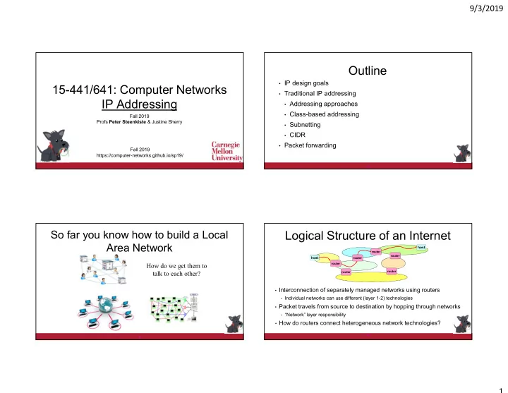
Logical Structure of an Internet

  • Interconnection of separately managed networks using routers
  • Individual networks can use different (layer 1-2) technologies
  • Packet travels from source to destination by hopping through networks
  • “Network” layer responsibility
  • How do routers connect heterogeneous network technologies?

4

host

router router router router router router

host

slide-2
SLIDE 2

9/3/2019 2

Solution: Internet Protocol (IP)

  • Inter-network connectivity provided by

the Internet protocol

  • Hosts use Internet Protocol to send

packets destined across networks.

  • IP creates abstraction layer that hides

underlying technology from network application software

  • Allows range of current & future technologies
  • WiFi, traditional and switched Ethernet,

personal area networks, …

5

Network Technology Network Applications

email WWW phone... SMTP HTTP RTP... TCP UDP… IP ethernet PPP… CSMA async sonet... copper fiber radio...

The Packet as an Envelope

6

HTTP Packet Payload: GET nyan.cat…. Local Address Header (Ethernet, WiFI) To: Destination Host From: Sender Host Host wants to send… But need a local addressing header to travel between routers IP Header To: 123.45.67.89 (Destination Host) From: 169.229.49.157 (Sender Host) IP address identifies final destination

The Packet as an Envelope

7

HTTP Packet Payload: GET nyan.cat…. IP Header To: 123.45.67.89 (Destination Host) From: 169.229.49.157 (Sender Host) Local Address Header (Ethernet, WiFi) To: Destination Host From: Local Router Datalink headers may differ across networks Host wants to send… But need a local addressing header to travel between routers IP address identifies final destination But IP header remains unchanged!

Set of Envelopes Traveling through the Internet

  • Source adds all headers (HTTP, transport -> PHY)
  • Each router:
  • Removes datalink layer
  • Uses IP header to make forwarding decision
  • Adds data link layer header for next network
  • Destination removes all headers (PHY -> HTTP)

host

router router router router router router

host

HTTP Packet Payload: GET nyan.cat…. Datalink Header To: Next hop router From: This router IP Header To: 123.45.67.89 From: 169.229.49.157

slide-3
SLIDE 3

9/3/2019 3

What are the Goals?

  • LANs: “Connect hosts”  switching:
  • Only has to scale up a “LAN size”
  • Availability
  • Internet: “Connect networks”  routing:
  • Scalability
  • Manageability of individual networks – essential to

achieving scalability

  • Availability
  • Affects addressing, protocols, routing

10

Outline

  • IP design goals
  • Traditional IP addressing
  • Addressing approaches
  • Class-based addressing
  • Subnetting
  • CIDR
  • Packet forwarding

11

Addressing and Forwarding

  • Flat address space with smart routers
  • Packets carry a destination address
  • Routers knows how to reach every host
  • Flat address space with dumb routers
  • Packet header specifies the path the packet should take
  • Hierarchical address space
  • What we actually do in IP – our focus today
  • Table of circuit identifiers
  • More on this later in the course

12

Flat Address Forwarding

  • Bridge/switch has a table that shows for each

MAC Address which port to use for forwarding

  • For every packet, the bridge “looks up” the entry for the packets

destination MAC address and forwards the packet on that port.

  • Other packets are broadcast – why?
  • Timer is used to flush old entries

8711C98900AA

2

MAC Address Port

A21032C9A591

1

99A323C90842

2

301B2369011C

2

695519001190

3

15

Age

36 01 16 11

Bridge

1 3 2

14

slide-4
SLIDE 4

9/3/2019 4

Flat Address Forwarding

  • Bridge/switch has a table that shows for each

MAC Address which port to use for forwarding

  • For every packet, the bridge “looks up” the entry for the packets

destination MAC address and forwards the packet on that port.

  • Other packets are broadcast – why?
  • Timer is used to flush old entries

8711C98900AA

2

MAC Address Port

A21032C9A591

1

99A323C90842

2

301B2369011C

2

695519001190

3

15

Age

36 01 16 11

Bridge

1 3 2

Each router tracking 2^32 addresses = scalability nightmare

16

Why is this not a good solution for the Internet?

Source Routing

  • List entire path in packet
  • Driving directions (north 3 hops, east, etc..)
  • Router processing
  • Strip first step from packet
  • Examine next step in directions and forward
  • Defined for IPv4 but rarely used
  • End points need to know a lot about network
  • Economic and security concerns
  • Variable header size

15

Hierarchical Addressing

  • Flat addresses – one address for every host
  • My laptop: 1234-5067-8901
  • Does not scale – router table size explodes – 4.4 Billion and counting!
  • Hierarchical – add structure
  • Postal address: US / PA / Pittsburgh / CMU / Gates / 9th fl / Steenkiste
  • Common “trick” to simplify forwarding, reduce forwarding table sizes
  • What type of hierarchy do we need for the Internet?
  • How many levels?
  • Same hierarchy depth for everyone?
  • Who controls the hierarchy?

16

IP Addresses (IPv4)

  • Unique 32-bit number associated with a host
  • Represented with the “dotted quad” notation
  • e.g., 12.34.158.5

00001100 00100010 10011110 00000101

12 34 158 5

00001100 00100010 10011110 00000101

19

slide-5
SLIDE 5

9/3/2019 5

Hierarchy in IP Addressing

  • 32 bits are partitioned into a prefix and suffix components
  • Prefix is the network component: CMU
  • Suffix is host component: Prof. Sherry’s laptop at CMU
  • Interdomain routing operates on the network prefix
  • Destination network operates on the host component

00001100 00100010 10011110 00000101

Network (23 bits) Host (9 bits) 12 34 158 5

21

History of Internet Addressing

  • Always dotted-quad notation
  • Always network/host address split
  • But nature of that split has changed over time

22

Original Internet Addresses

  • First eight bits: network component
  • Last 24 bits: host component

Assumed 256 networks were more than enough!

23

IP Address Structure, ca 1981

Routers know how to get to network ID, but not individual hosts.

Network ID Host ID

Network ID Host ID 8 16

Class A

32

Class B

10

Class C 110 Multicast Addresses Class D

1110

Reserved for experiments Class E

1111

24

24

slide-6
SLIDE 6

9/3/2019 6

IP Route Lookup, ca 1981

  • Router extracts address class and network ID from IP address
  • Forwarding table structure reflects address structure
  • Logically, a separate forwarding table for each address class
  • For unicast address (classes A-C) entries contain
  • The prefix for a destination network (length 8/16/24)
  • Information on how to forward the packet, e.g., exit port, ..
  • www.cmu.edu address 128.2.11.43
  • Class B address – class + network is 128.2
  • Lookup 128.2 in forwarding table for class B
  • Tables are still large!
  • 2 Million class C networks

23

Outline

  • IP design goals
  • Traditional IP addressing
  • Addressing approaches
  • Class-based addressing
  • Subnetting
  • CIDR
  • Packet forwarding

24

Subnetting

  • Adds another layer to hierarchy
  • Network can be split into multiple subnets
  • Prefix of the subnet is Network and (variable length) Subnet identifiers
  • Subnetting is done internally in the organization
  • It is not visible outside – important for management

25

Network Host Network Host Subnet

1 1 1 1 1 1 1 1 1 1 1 1 1 1 1 1 1 1 1 1 1 1 1 1 0 0 0 0 0 0 0 0

Subnet Mask

Subnet Addressing RFC 917 (1984)

  • The Internet was growing and some “LANs” were very big
  • Can no longer be managed as a single LAN
  • Too many hosts spread across multiple departments
  • Some protocols become inefficient
  • Need a simple way to partition large networks
  • Partition into multiple IP networks with different (subnet) prefixes
  • Subnets are connected by routers – how do they learn subnet length?
  • CMU case study in RFC
  • Chose not to adopt – concern that it would not be widely supported 

34

slide-7
SLIDE 7

9/3/2019 7

IP Address Problem (1991)

  • Address space depletion: class-based addressing is inefficient
  • Suppose you need 216 + 1 addresses?
  • Class A block is too big for all but a few domains
  • Class C block too small for many domains but they don’t need a class B
  • Class B address pool was being allocated at a high rate
  • Many allocated address block are sparsely used
  • IETF developed a strategy based on three solutions
  • Switch to a “classless” addressing model – this lecture
  • Network address translation (NAT) – next week
  • Definition of IPv6 with larger IP addresses – next week

27

Today’s Addressing: CIDR

  • CIDR = Classless Interdomain Routing
  • Idea: Flexible division between network and host addresses
  • Not limited to three sizes 8/16/24
  • Prefix can be any size
  • Similar to subnets!
  • Motivation: more efficient use of the IP address space
  • But seems hard to manage!
  • How do we limit the size of forwarding tables

27

CIDR (example)

  • Suppose a network has fifty computers
  • Allocate 6 bits for host addresses (since 25 < 50 < 26)
  • Remaining 32 - 6 = 26 bits as network prefix
  • Flexible boundary means the boundary must be explicitly specified

with the network address!

  • Informally, “slash 26”  128.23.9/26
  • Formally, prefix represented with a 32-bit mask: 255.255.255.192

where all network prefix bits set to “1” and host suffix bits to “0”

  • This works for people, but how about prefixes in routers and packets?

28

IP Addressing: Hierarchical

  • CIDR allows more efficient use of the IP address space
  • Helps (at least for a while) with the high demand for IP addresses
  • But how does this help with the growth of forwarding tables?
  • Number of destination networks is growing as well!
  • Solution has two complementary parts:
  • Allocation of IP addresses is done hierarchically based on network

topology

  • Routers will combine forwarding entries for destinations “in the

same general direction”

30

slide-8
SLIDE 8

9/3/2019 8

Example: Sending a Letter

US / PA / Pittsburgh / CMU / Gates / 9th fl / Steenkiste

Example: Made It to PA

US / PA / Pittsburgh / CMU / Gates / 9th fl / Steenkiste

Example: and Pittsburgh

US / PA / Pittsburgh / CMU / Gates / 9th fl / Steenkiste

Example: Made It!

US / PA / Pittsburgh / CMU / Gates / 9th fl / Steenkiste

slide-9
SLIDE 9

9/3/2019 9

Address Allocation is Done Hierarchically

  • Historically assignment of prefixes was “first come first serve”
  • With CIDR: Internet Corporation for Assigned Names and Numbers

(ICANN) gives large blocks to…

  • Regional Internet Registries, such as the American Registry

for Internet Names (ARIN), which give blocks to…

  • Large institutions (ISPs), which give addresses to …
  • Individuals and smaller institutions
  • FAKE Example:

ICANN  ARIN  AT&T  UCB  EECS

31

CIDR: Addresses Allocated in Contiguous Prefix Chunks

Recursively break down chunks as get closer to host 12.0.0.0/8 12.0.0.0/15 12.253.0.0/16 12.2.0.0/16 12.3.0.0/16

: :

12.3.0.0/24 12.3.4.0/22 : : 12.3.254.0/23 12.253.0.0/19 12.253.32.0/19 12.253.64.0/19 12.253.64.108/30 12.253.96.0/18 12.253.128.0/17 : : :

:

32

ARIN AT&T UCB EECS Subnet

IP Addressing  Scalable Forwarding?

  • How many forwarding entries does

France Telecom need for LBL/UCB destinations?

  • How about if all a.0.0.0/8 addresses are served by

AT&T - it “own” a.0.0.0/8, right?

  • In practice, it is complicated …

AT&T a.0.0.0/8 France Telecom LBL a.b.0.0/16 UCB a.c.0.0/16

a.c.*.* is this way a.b.*.* is this way

Two One

35

Limiting Forward Table Sizes

39

201.10.0.0/21 201.10.0.0/22 201.10.4.0/24 201.10.5.0/24 201.10.6.0/23

Provider 1 Provider 2

201.11.5.0/21

Advertise

Merged Advertisement For All Customers

slide-10
SLIDE 10

9/3/2019 10

CIDR Implication: Longest Prefix Match

  • How to deal with multi-homing, legacy addresses, …

40 201.10.0.0/21 201.10.0.0/22 201.10.4.0/24 201.10.5.0/24 201.10.6.0/23 (or Provider 2 address)

Provider 1 Provider 2

201.10.6.0/23

Advertise

How LPM Works

  • Routing protocols aggregate forwarding entries to reduce table size
  • E.g., 3 forwarding entries A/B/C 01010011.xy/10 can be combined

into 01010011/8 if they forward through the same port

  • A fourth entry D that uses a different egress port has its own entry
  • Works correctly because of longest prefix match (LPM)
  • Packets to A/B/C will match only the 01010011/8
  • Packets to D will match entries but will prefer the short “/10” entry
  • Legacy prefixes (e.g., 128.2) also often have their own entry

Filling in Some Router Details

  • How do routing protocols learn the prefix size?
  • Routing advertisements include the prefix size
  • For stub networks (subnetting): routers are configured by admin
  • But a router now needs ~30 forwarding tables?
  • No – forwarding uses a single tree data structure (called a trie)
  • Very efficient algorithms exist for look up both in HW and SW
  • How do routers know the prefix size for destination addresses?
  • They do not need them because of how LPM look up works