On Base & Limit Base & Bound MAX sys Contiguous Allocation: - - PowerPoint PPT Presentation

on base limit
SMART_READER_LITE
LIVE PREVIEW

On Base & Limit Base & Bound MAX sys Contiguous Allocation: - - PowerPoint PPT Presentation

More Multiplexing More Multiplexing At different times, different processes can map At different times, different processes can map part of their virtual address space into the part of their virtual address space into the same physical memory


slide-1
SLIDE 1

More Multiplexing

At different times, different processes can map part of their virtual address space into the same physical memory

pi pj

More Multiplexing

At different times, different processes can map part of their virtual address space into the same physical memory

pi pj

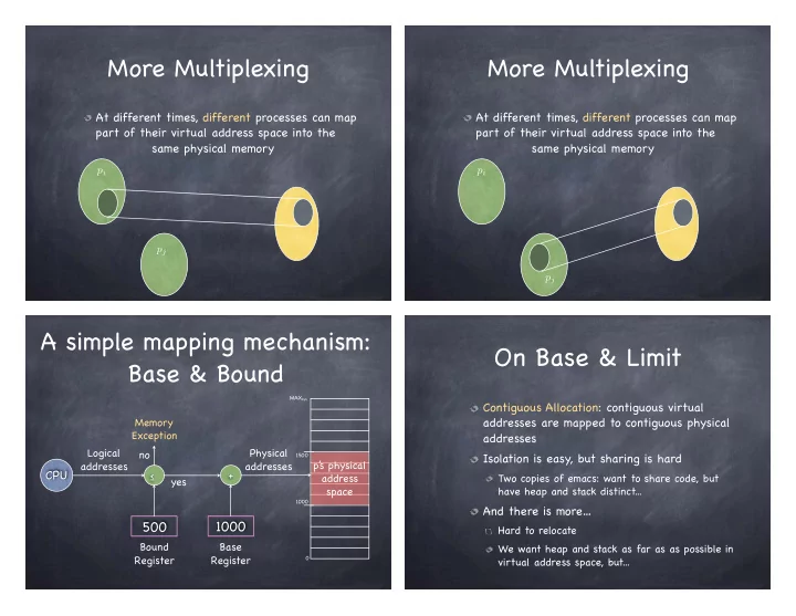
A simple mapping mechanism: Base & Bound

CPU

Bound Register Base Register

1500 1000 MAXsys

500 1000

p’ s physical address space ≤ + yes no Memory Exception Logical addresses Physical addresses

On Base & Limit

Contiguous Allocation: contiguous virtual addresses are mapped to contiguous physical addresses Isolation is easy, but sharing is hard

Two copies of emacs: want to share code, but have heap and stack distinct...

And there is more…

Hard to relocate We want heap and stack as far as as possible in virtual address space, but...

slide-2
SLIDE 2
  • III. Timer Interrupts

Hardware timer can be set to expire after specified delay (time or instructions) when it does, control is passed back to the kernel Other interrupts (e.g. I/O completion) also give control to kernel

Interrupt Management

Interrupt controllers implements interrupt priorities: Interrupts include descriptor of interrupting device Priority selector circuit examines all interrupting devices, reports highest level to the CPU more on this later… interrupt controller

interrupt

Interrupt Management

Maskable interrupts can be turned off by the CPU for critical processing Nonmaskable interrupts indicate serious errors (power out warning, unrecoverable memory error, etc.) interrupt controller

interrupt

Interrupt-driven I/O

Memory-mapped I/O

Device communicate over the memory bus I/O ops by dedicated device hardware correspond to reads/writes to special addresses Devices appear as if part

  • f the memory address

space

slide-3
SLIDE 3

Interrupt-driven I/O

Memory-mapped I/O

Device communicate over the memory bus I/O ops by dedicated device hardware correspond to reads/writes to special addresses Devices appear as if part

  • f the memory address

space

Interrupt driven ops with memory-mapped I/O

CPU initiates device op (e.g., disk read): writes op descriptor to designated memory location CPU continues its regular computation Device asynchronously performs op; when op completes, interrupts the CPU Could happen for each byte read!

From interrupt-driven I/O to DMA

Interrupt driven I/O

Device CPU RAM

CPU issues read request device interrupts CPU with data CPU writes data to memory for (i = 1 . . . n)

Disk

From interrupt-driven I/O to DMA

Interrupt driven I/O

Device CPU RAM

CPU issues read request device interrupts CPU with data CPU writes data to memory

+ Direct Memory Access

Device RAM

CPU sets up DMA request Device puts data on bus & RAM accepts it Device interrupts CPU when done for (i = 1 . . . n) for (i = 1 . . . n)

Disk Disk

From user mode to kernel mode...

Interrupts

HW device requires OS service

timer, I/O device, interprocessor

asynchronous

Exceptions

user program acts silly (e.g. division by zero) attempt to perform a privileged instruction

sometime on purpose! (breakpoints)

synchronous

System calls/traps

user program requests OS service

synchronous

slide-4
SLIDE 4

...and viceversa

User-level upcall

a sort of user-level interrupt handling

q If new process

copy program in memory, set PC and SP toggle mode p

Resume after exception, interrupt or syscall

restore PC, SP, registers; toggle mode

Switch to different process

load PC, SP, registers from ’ s PCB toggles mode

q

Making the transition: Safe mode switch

Common sequences of instructions to cross boundary, which provide: Limited entry

entry point in the kernel set up by kernel

Atomic changes to process state

PC, SP, memory isolation, mode

Transparent restartable execution

user program must be restarted exactly as it was before kernel got control

Interrupt vector

handleTimerInterrupt() { ... } 31 handleDivideByZero() { ... } 128 255 handleTrap() { ... } 32

Processor Register Interrupt Vector

Hardware identifies why boundary is crossed trap? interrupt (which device)? exception? Hardware selects entry from interrupt vector Appropriate handler is invoked

Interrupt stack

Pointed by privileged register Stores execution context of interrupted process

HW saves SP, PC Handler saves remaining registers

Stores handler’ s local variables One interrupt stack per process (or per thread!)

Why not use the stack in user’ s space?

Reliability: user-level stack pointer may not be valid Security: on a multiprocessor, another thread could modify return address for kernel, jumping to arbitrary code

slide-5
SLIDE 5

Interrupt masking

What if an interrupt occurs while running an interrupt handler? Disable interrupts via privileged instruction

Overdramatic… it actually defers them

Just use the current SP of Interrupt stack

Mode switch on x86

User-level Process Registers Kernel

Code

foo() { while(...) { x = x+1; y = y-2 } }

Stack Code

handler() { pusha ... }

Interrupt Stack EFLAGS Other Registers: EAX, EBX, ... SS:ESP

Stack segment Offset

CS:EIP

Code segment Offset

Stack pointer Program counter Flags

Mode switch on x86

User-level Process Registers Kernel

Code

foo() { while(...) { x = x+1; y = y-2 } }

Stack Code

handler() { pusha ... }

Interrupt Stack Other Registers: EAX, EBX, ... EFLAGS SS:ESP CS:EIP

  • 1. Change mode bit
  • 2. Disable interrupts
  • 3. Save key registers to temporary location
  • 4. Switch onto the kernel interrupt stack

EFLAGS SS:ESP CS:EIP

Stack pointer Program counter Flags

Hardware performs these steps

Mode switch on x86

User-level Process Registers Kernel

Code

foo() { while(...) { x = x+1; y = y-2 } }

Stack Code

handler() { pusha ... }

Interrupt Stack Other Registers: EAX, EBX, ... EFLAGS SS:ESP CS:EIP

  • 1. Change mode bit
  • 2. Disable interrupts
  • 3. Save key registers to temporary location
  • 4. Switch onto the kernel interrupt stack
  • 5. Push key registers onto new stack

EFLAGS SS:ESP CS:EIP

Hardware performs these steps

slide-6
SLIDE 6

Mode switch on x86

User-level Process Registers Kernel

Code

foo() { while(...) { x = x+1; y = y-2 } }

Stack Code

handler() { pusha ... }

Interrupt Stack Other Registers: EAX, EBX, ... EFLAGS SS:ESP CS:EIP

  • 1. Change mode bit
  • 2. Disable interrupts
  • 3. Save key registers to temporary location
  • 4. Switch onto the kernel interrupt stack
  • 5. Push key registers onto new stack

EFLAGS SS:ESP CS:EIP

Hardware performs these steps

Mode switch on x86

User-level Process Registers Kernel

Code

foo() { while(...) { x = x+1; y = y-2 } }

Stack Code

handler() { pusha ... }

Interrupt Stack Other Registers: EAX, EBX, ... EFLAGS SS:ESP CS:EIP

  • 1. Change mode bit
  • 2. Disable interrupts
  • 3. Save key registers to temporary location
  • 4. Switch onto the kernel interrupt stack
  • 5. Push key registers onto new stack
  • 6. Save error code (optional)

EFLAGS SS:ESP CS:EIP Error

Hardware performs these steps

Software (handler) performs this step

Mode switch on x86

User-level Process Registers Kernel

Code

foo() { while(...) { x = x+1; y = y-2 } }

Stack Code

handler() { pusha ... }

Interrupt Stack Other Registers: EAX, EBX, ... EFLAGS SS:ESP CS:EIP

EFLAGS SS:ESP CS:EIP Error

  • 8. Handler pushes all registers on stack
  • 1. Change mode bit
  • 2. Disable interrupts
  • 3. Save key registers to temporary location
  • 4. Switch onto the kernel interrupt stack
  • 5. Push key registers onto new stack
  • 6. Save error code (optional)

7 . Transfer control to interrupt handler

Hardware performs these steps

slide-7
SLIDE 7
  • 1. Change mode bit
  • 2. Disable interrupts
  • 3. Save key registers to temporary location
  • 4. Switch onto the kernel interrupt stack
  • 5. Push key registers onto new stack
  • 6. Save error code (optional)

7 . Transfer control to interrupt handler

Hardware performs these steps

Mode switch on x86

User-level Process Registers Kernel

Code

foo() { while(...) { x = x+1; y = y-2 } }

Stack Code

handler() { pusha ... }

Interrupt Stack Other Registers: EAX, EBX, ... EFLAGS SS:ESP CS:EIP

EFLAGS SS:ESP CS:EIP Error

  • 8. Handler pushes all registers on stack

Software (handler) performs this step

Mode switch on x86

User-level Process Registers Kernel

Code

foo() { while(...) { x = x+1; y = y-2 } }

Stack Code

handler() { pusha ... }

Interrupt Stack Other Registers: EAX, EBX, ... EFLAGS SS:ESP CS:EIP

EFLAGS SS:ESP CS:EIP Error All Registers: SS, ESP, EAX, EBX,...

  • 8. Handler pushes all registers on stack

Software (handler) performs this step

  • 1. Change mode bit
  • 2. Disable interrupts
  • 3. Save key registers to temporary location
  • 4. Switch onto the kernel interrupt stack
  • 5. Push key registers onto new stack
  • 6. Save error code (optional)

7 . Transfer control to interrupt handler

Hardware performs these steps

Switching back

From an interrupt, handler reverses all steps!

pops registers saved on the stack executes instruction that restore PC, SP, and EFLAGS

From exception and system call, increment PC

  • n return
  • n exception, handler changes PC at the base of

the stack

  • n system call, increment is done by hw when

saving user level state