
SLIDE 1
Wireless Ad Hoc and Sensor Networks
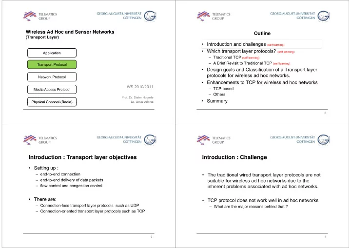
(Transport Layer)
Application Transport Protocol N k P l
WS 2010/2011
Network Protocol Media Access Protocol
- Prof. Dr. Dieter Hogrefe
- Dr. Omar Alfandi
Media Access Protocol Physical Channel (Radio)
- Dr. Omar Alfandi
Physical Channel (Radio)
Outline Out e
- Introduction and challenges (self learning)
- Which transport layer protocols? (self learning)
– Traditional TCP (self learning) A B i f R i it t T diti l TCP – A Brief Revisit to Traditional TCP (self learning)
- Design goals and Classification of a Transport layer
protocols for wireless ad hoc networks protocols for wireless ad hoc networks.
- Enhancements to TCP for wireless ad hoc networks
– TCP-based TCP based – Others
- Summary
y
2
Introduction : Transport layer objectives Introduction : Transport layer objectives
- Setting up :
– end-to-end connection – end-to-end delivery of data packets flow control and congestion control – flow control and congestion control
- There are:
- There are:
– Connection-less transport layer protocols such as UDP – Connection-oriented transport layer protocols such as TCP p y p
3
Introduction : Challenge Introduction : Challenge
- The traditional wired transport layer protocols are not
suitable for wireless ad hoc networks due to the inherent problems associated with ad hoc networks inherent problems associated with ad hoc networks. TCP protocol does not
- rk
ell in ad hoc net orks
- TCP protocol does not work well in ad hoc networks
– What are the major reasons behind that ?
4