
SLIDE 1
Page 1 on 32 General presentation Challenger7
General presentation of Challenger7
Release: V1.00 – 10/11/2018
http://www.skynam.com
Machine management
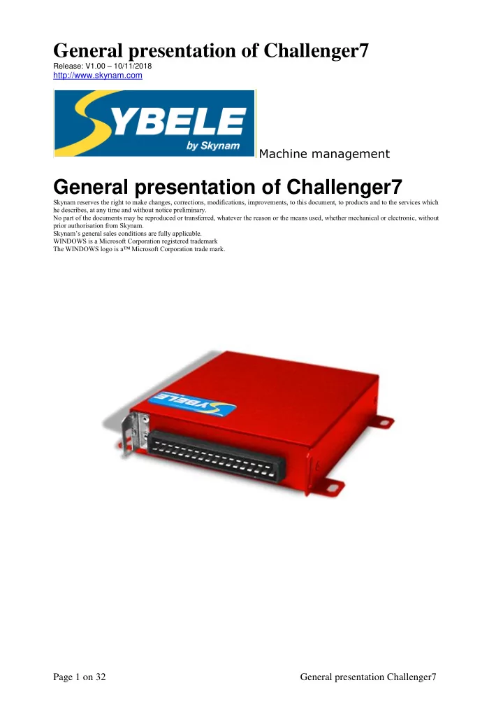
General presentation of Challenger7
Skynam reserves the right to make changes, corrections, modifications, improvements, to this document, to products and to the services which he describes, at any time and without notice preliminary. No part of the documents may be reproduced or transferred, whatever the reason or the means used, whether mechanical or electronic, without prior authorisation from Skynam. Skynam’s general sales conditions are fully applicable. WINDOWS is a Microsoft Corporation registered trademark The WINDOWS logo is a™ Microsoft Corporation trade mark.