d + d T T u F dV u F dS b s V S (1) ( ) 2 - - PDF document

d d t t u f dv u f ds b s v s 1 2 formulations d t r d t
SMART_READER_LITE
LIVE PREVIEW

d + d T T u F dV u F dS b s V S (1) ( ) 2 - - PDF document

18 TH INTERNATIONAL CONFERENCE ON COMPOSITE MATERIALS FLUTTER SPEED ESTIMATION FOR FOLDING WING SYSTEM Y. Jung 1 J. Kim 2 * 1 School of Mechanical and Aerospace Eng., Seoul National Univ., Seoul, Korea, 2 Institute of Advanced Aerospace Technology,


slide-1
SLIDE 1

18TH INTERNATIONAL CONFERENCE ON COMPOSITE MATERIALS

1 Introduction Recently, morphing aircrafts with multiple mission capabilities are developed by several projects such as NASA or Defense Advanced Research Projects Agency. One of the morphing concepts is the folding wing system with out-of- plane motion. It can adjust flight performance from a cruise configuration to a high speed configuration. A typical procedure of aeroelastic analysis, there are several parameters with important roles, such as fold angle and hinge stiffness. According to Ref. [1], the folding structural natural frequency and the flutter velocity are sensitive to the angle and the hinge stiffness. On the other hand, Flutter speed can be controlled by ply angle of a laminated composite plate due to directional dependency of strength and stiffness of a material. In presented work, the structure is modeled by using Finite Element Method (FEM) and the flow is analyzed by Doublet Lattice Method (DLM). Additionally, the PK method is obtained for aeroelastic analysis. 2 Formulations 2.1 Structural modeling The wing consists of three parts as body, inboard and outboard component. All parts are assumed as plates and distributed hinge spring connects each of

  • them. The spring is assumed to have negligible mass

compared with the wing. The initial fold angles are

1

f and

2

f , and these are the static equilibrium

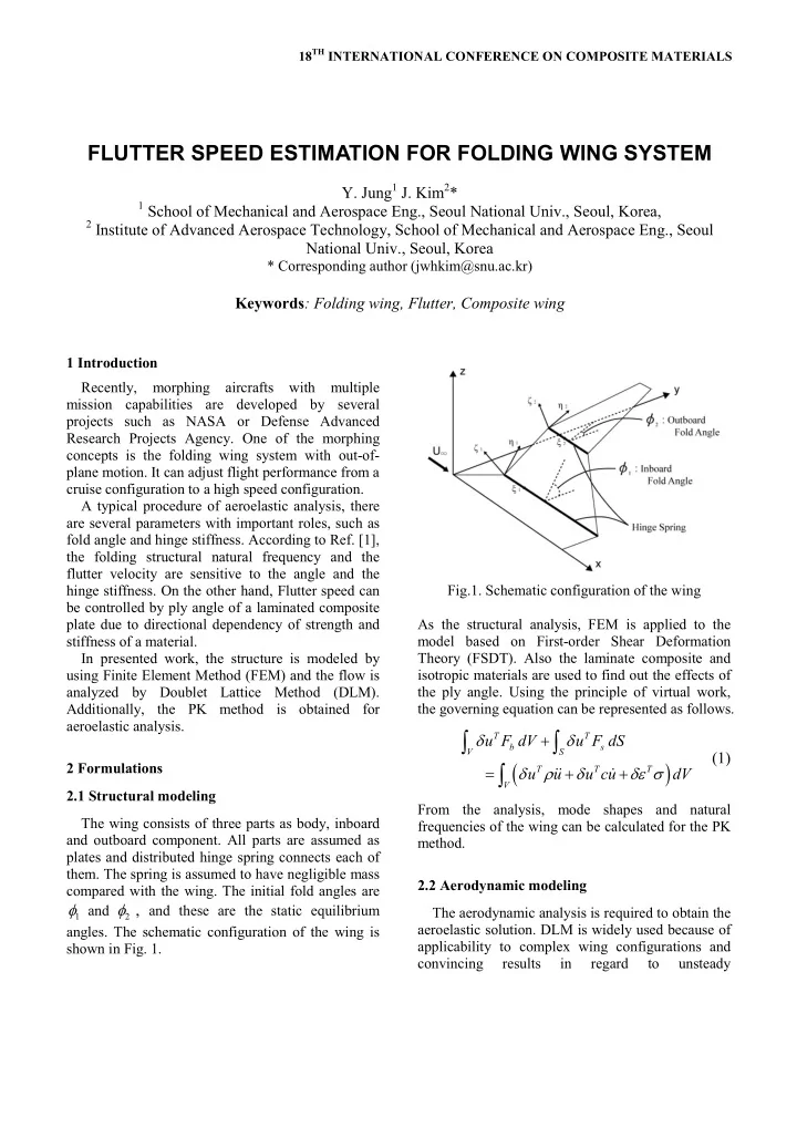
  • angles. The schematic configuration of the wing is

shown in Fig. 1. Fig.1. Schematic configuration of the wing As the structural analysis, FEM is applied to the model based on First-order Shear Deformation Theory (FSDT). Also the laminate composite and isotropic materials are used to find out the effects of the ply angle. Using the principle of virtual work, the governing equation can be represented as follows.

( )

T T b s V S T T T V

u F dV u F dS u u u cu dV d d d r d de s + = + +

ò ò ò

&& & (1)

From the analysis, mode shapes and natural frequencies of the wing can be calculated for the PK method. 2.2 Aerodynamic modeling The aerodynamic analysis is required to obtain the aeroelastic solution. DLM is widely used because of applicability to complex wing configurations and convincing results in regard to unsteady

FLUTTER SPEED ESTIMATION FOR FOLDING WING SYSTEM

  • Y. Jung1 J. Kim2*

1 School of Mechanical and Aerospace Eng., Seoul National Univ., Seoul, Korea, 2 Institute of Advanced Aerospace Technology, School of Mechanical and Aerospace Eng., Seoul

National Univ., Seoul, Korea

* Corresponding author (jwhkim@snu.ac.kr)

Keywords: Folding wing, Flutter, Composite wing

slide-2
SLIDE 2
  • aerodynamics. Moreover, Aerodynamic Influence

Coefficients (AIC) can be calculated directly. The procedure is started from Euler’s equations with five unknown variables, air density, pressure and three velocity components. With the continuity equation, isentropic relation, velocity potential and small disturbance component, as a result, the following matrix notation can be obtained.

{ } [ ]{ }

w Q p = (2)

where Q is the normalwash factor from the combined effects of the steady vortices and the

  • scillatory doublets and it is the AIC.

2.3 Aeroelastic modeling From the DLM, the AIC matrix is calculated as a function of reduced frequency k and Mach number

a

M with N N ´

size where N is total number of elements of the aerodynamic model. The size of the coefficient matrix needs to be reduced to n

n ´

for modal flutter analysis where n is number of natural modes used in the analysis. The mathematical transformation procedure is expressed as

[ ] [ ] [ ] [ ][ ][ ]

T T nn mn Nm NN Nm mn

Q G Q G = F F (3)

where

nn

Q

is the generalized aerodynamic matrix,

mn

F

is a matrix of n-set normal mode vectors and

Nm

G

is the spline matrix for matching the aerodynamic and structural mesh. For the aeroelastic analysis, the PK method is performed. The fundamental equation for modal flutter analysis is

{ }

2 2

1 / 2 1 2

I hh hh hh R hh hh h

M p B bVQ k p K V Q u r r é æ ö +

  • ç

÷ ê è ø ë ù æ ö +

  • =

ç ÷ú è øû (4)

The eigenvalues will be complex conjugate pairs and the oscillatory solutions require an iterative solution. The principal advantage of the PK method is producing results directly for given velocity. 3 Results and Discussions 3.1 Validation With these formulations, the validation is performed by using 15 degree-sweptback wing model in Ref. [3]. The natural frequencies and mode shapes are equivalent to the results of the reference. Also the flutter speed and frequency from the PK method are well agreed with the presented results as shown in Table 1. Table 1. Validation of flutter speed and frequency Analysis Type

f

V (ft/sec)

f

w (Hz)

Method PATRAN 483 113 KE Present 496 108 PK 3.2 The effect of ply angle In the current study, the angle of the outboard wing is assumed as constant. Thus, the results are computed using these parameters, fold angle of inboard wing, hinge stiffness and ply angle of laminates. And two materials are

  • btained,

aluminum and T300/5208 Graphite/Epoxy. To compare the tendency of two models, two models make have same mass by control the thickness. A number of total aerodynamic elements is 324 and structural elements is 260. Computational results for an inboard wing fold angle of 0 to 85 deg with 5 deg

  • increment. For simplicity of study, the ply angle is

determined as [

]

2 2

0 /

S

q

. Additionally, the geo- metric configuration is represented in Table 2.

Table 2. Geometry of the folding wing model [4] Chord Body 180 (root) 144 (tip) Inboard 144 60 Outboard 60 21 Span Body 36 Inboard 54 Outboard 84 Sweepback Angle (deg) 45 Thickness Isotropic Plate 1.05 Composite Plate 1.80

slide-3
SLIDE 3

3 FLUTTER SPEED ESTIMATION FOR FOLDING WING SYSTEM

(a) Flutter dynamic pressure vs. ply angle (b) Flutter frequency vs. ply angle

  • Fig. 2. The effect of ply angle

As shown in Fig. 2, the flutter dynamic pressure is changed dynamically. When the fold angle is 0 deg, effect of ply angle is not large. However, as the fold angle larger, the effect

  • increases. The largest average flutter dynamic

pressure is obtained at 60 deg, ply angle.

3.3 The effect of fold angle

The analysis is performed in range of 0 to 85 deg fold angles with 5 deg increments for the first five modes. (a) Flutter dynamic pressure vs. fold angle (a) Flutter dynamic pressure vs. fold angle

  • Fig. 3. The effect of fold angle

As shown in Fig. 3 (a), the flutter dynamic pressure is increased at 55 deg. Also Fig. 3(b) shows the relation between the flutter frequency and the flutter dynamic pressure. When there is a large increment of the pressure, the flutter frequency is also varied largely. Fig. 4 and 5 are

slide-4
SLIDE 4

shows V-g and V-f plots for 55 deg and 60 deg which has large increments of the pressure. (a) V-g plot (b) V-f plot

  • Fig. 4. V-g and V-f plots for 55 deg, fold angle

As shown in Fig. 4, 2nd mode and 3rd mode are coupled and flutter is occurred at 3rd mode. However, in Fig. 5, coupled modes are changed to 3rd and 4th mode. Moreover, flutter is

  • ccurred at 4th mode. During fold angle

increases 5 degree, the flutter mode is changed from 3rd to 4th mode. Due to this situation, the flutter dynamic pressure is very sensitive to the fold angle variation. (a) V-g plot (b) V-f plot

  • Fig. 5. V-g and V-f plots for 60 deg, fold angle

3.3 The effect of hinge stiffness

The effect of the hinge stiffness on the flutter boundary of the folding wing structure are

  • considered. The boundary is measured for 4 fold

angles with 6 hinge stifness values. As shown in

  • Fig. 4, flutter boundaries have almost constant

value before

6

10 / lb in rad × and then variation

slide-5
SLIDE 5

5 FLUTTER SPEED ESTIMATION FOR FOLDING WING SYSTEM

starts from

8

10 / lb in rad × for an isotropic plate model.

(a) Flutter dynamic pressure vs. hinge stiffness (b) Flutter frequency vs. hinge stiffness

Fig.4. The effect of hinge stiffness for isotropic plate model

On the other hand, in case of a composite plate model, variation is more apparent than a case of the isotropic plate model. When the fold angle is 60 deg, the flutter dynamic pressure almost increases twice. (a) Flutter dynamic pressure vs. hinge stiffness (b) Flutter frequency vs. hinge stiffness

Fig.5. The effect of hinge stiffness for composite plate model 4 Conclusions

The aeroelastic stability of a folding wing model is studied using finite element method based on laminated composite theory and FSDT, doublet lattice method and PK method. The results are calculated for various fold angles, hinge stiffness and ply angles of laminates.

slide-6
SLIDE 6

The effect of the parameters is obtained and

  • bviously the flutter boundaries are very

sensitive to them. According to the results the composite plate model is more stable than the isotropic plate model when the ply angle is 60 deg.

References

[1] S. Liska and E. H. Dowell “Continuum Aeroelastic Model for a Folding-Wing Configuration”. AIAA,

  • Vol. 47, No. 10, pp 2350-2358, 2009.

[2] Katz, J. and Plotkin, A “Low-Speed Aerodynamics”. 2nd edition, Cambridge, 2001. [3] Rodden, W. P., and Johnson, E.H, “MSC/NASTRAN Aeroelastic Analysis User's Guide”, Ver. 68, MSC, 2004. [4] Lee, D.H., and Chen, P.C., “Nonlinear Aeroelastic Studies on a Folding Wing Configuration with Free- play Hinge Nonlinearity”, AIAA, 47th AIAA/ASME /ASCE/AHS/ASC Structures, Structural Dynamics, and materials Conference, Newport, Rhode Island, 1- 4 May 2006.