
SLIDE 1
at Lewis Field
Glenn Research Center
Controls and Dynamics Branch
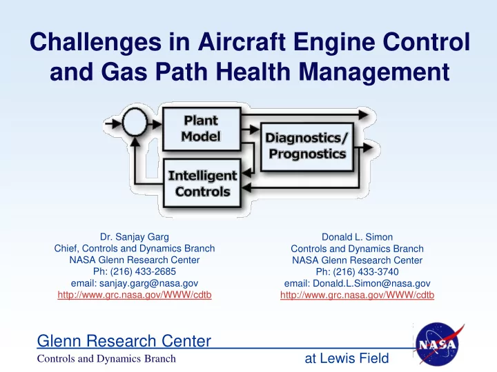
Challenges in Aircraft Engine Control and Gas Path Health Management
- Dr. Sanjay Garg
Chief, Controls and Dynamics Branch NASA Glenn Research Center Ph: (216) 433-2685 email: sanjay.garg@nasa.gov http://www.grc.nasa.gov/WWW/cdtb Donald L. Simon Controls and Dynamics Branch NASA Glenn Research Center Ph: (216) 433-3740 email: Donald.L.Simon@nasa.gov http://www.grc.nasa.gov/WWW/cdtb