Application of DICE (Dynamic Integrated Consequence Evaluation) Case - - PDF document

application of dice dynamic integrated consequence
SMART_READER_LITE
LIVE PREVIEW

Application of DICE (Dynamic Integrated Consequence Evaluation) Case - - PDF document

Transactions of the Korean Nuclear Society Virtual Spring Meeting July 9-10, 2020 Application of DICE (Dynamic Integrated Consequence Evaluation) Case Study on Branching Rules Examples Sejin Baek a , Taewan Kim b , Jonghyun Kim c , Gyunyoung Heo


slide-1
SLIDE 1

Application of DICE (Dynamic Integrated Consequence Evaluation) Case Study on Branching Rules Examples

Sejin Baeka, Taewan Kimb, Jonghyun Kimc, Gyunyoung Heoa

aKyung Hee University, 1732 Deogyeong-daero, Giheung-gu, Yongin-si, Gyeonggi-do, Republic of Korea, 17104 bInchoen National University, 119, Academy-ro, Yeonsu-gu, Incheon, Republic of Korea, 22012 cChosun University, 309, Pilmun-daero, Dong-gu, Gwangju, Republic of Korea, 61452 *Corresponding author: gheo@khu.ac.kr

  • 1. Introduction

PSA (Probabilistic Safety Assessment) consists of a static combination of FT (Fault Tree) and ET (Event Tree). The ET determines the branching points be defined the success criteria, mission time, operator action, etc. of the safety systems, which is setup by thermal-hydraulic calculation in advance. However, the conventional assessments have some difficulties in reviewing accident scenarios that are less obvious, such that optimistic or unidentified situations, dependency, and unexpected combinations of system malfunction and operator mistakes [1]. D-PSA (Dynamic PSA) is a method that incorporates deterministic and probabilistic methods to combine a reliability model and a thermal-hydraulic model. To implement D-PSA, therefore, a function that operates

  • ver time dependency and an ability to integrate a plant

physical model that derives deterministic results with an equipment model and an operator model that supports probabilistic results are required together. This study introduces the basic structure and conceptual design of DICE (Dynamic Integrated Consequence Evaluation). DICE is under development with the goal of checking the coverability of emergency

  • perational procedures on the basis of the DDET

(Discrete Dynamic Event Tree) method. In order to limit extremely huge number of simulations, DICE adopted the concept of ‘mutually exclusive and collectively exhaustive’ branching. Branching rules can simply be regarded as predetermined success criteria in conventional PSA. However, in D-PSA, it is expanded to develop various scenarios by subdividing or grouping conditions such that headings, branches, and success criteria. Developing scenarios through branching rules automatically creates an ET. Since the quantification of this ET works in conjunction with deterministic results, it is important to establish the method that can adequately quantify the probability of each branch generated and accident sequences. In addition, to generate branches dynamically by linking an accident scenario with the plant physical model, it is necessary to define branching rules that support diagnosis of branching points and generation of branches depending on an automatic or manual actuation for systems, components, or equipment. Since the overview of D-PSA and DICE have been presented through previous studies, this paper will describe extended examples and demonstrations [2, 3].

  • 2. Methods and Application

2.1 Structure of DICE DICE has been designed on the basis of the structures and functions of other D-PSA tools based on the notion

  • f DDET. For instance, the scheduler controls DDET

while the FT and HRA (Human Reliability Assessment) model are accompanied for diagnosis of branching

  • points. [4]. DICE has two separate modules which are

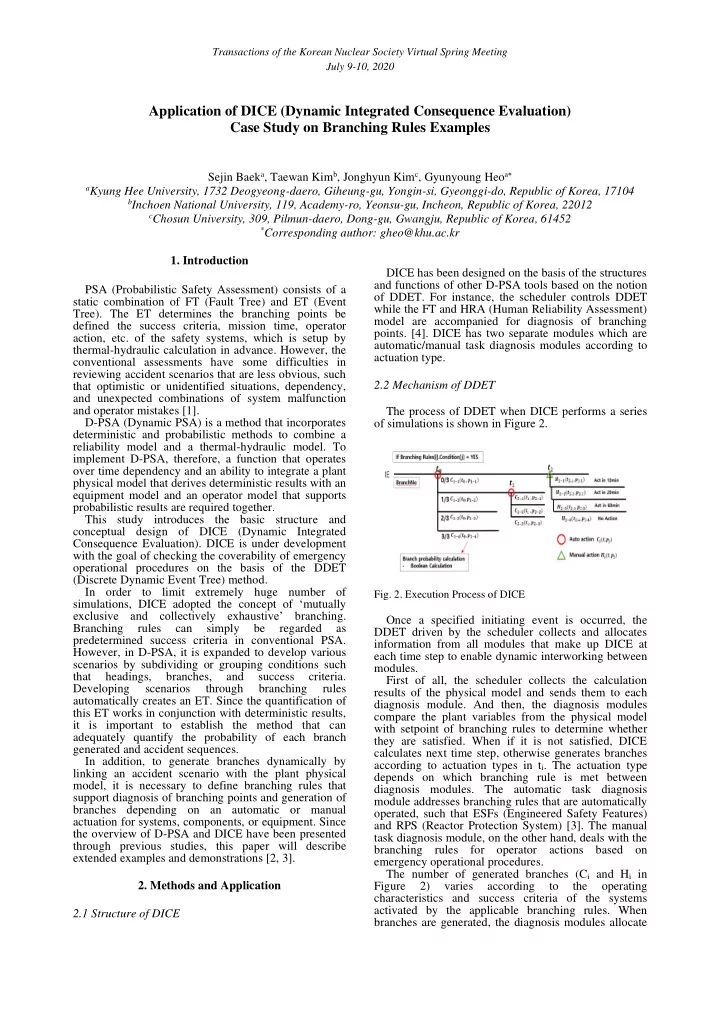
automatic/manual task diagnosis modules according to actuation type. 2.2 Mechanism of DDET The process of DDET when DICE performs a series

  • f simulations is shown in Figure 2.
  • Fig. 2. Execution Process of DICE

Once a specified initiating event is occurred, the DDET driven by the scheduler collects and allocates information from all modules that make up DICE at each time step to enable dynamic interworking between modules. First of all, the scheduler collects the calculation results of the physical model and sends them to each diagnosis module. And then, the diagnosis modules compare the plant variables from the physical model with setpoint of branching rules to determine whether they are satisfied. When if it is not satisfied, DICE calculates next time step, otherwise generates branches according to actuation types in ti. The actuation type depends on which branching rule is met between diagnosis modules. The automatic task diagnosis module addresses branching rules that are automatically

  • perated, such that ESFs (Engineered Safety Features)

and RPS (Reactor Protection System) [3]. The manual task diagnosis module, on the other hand, deals with the branching rules for operator actions based on emergency operational procedures. The number of generated branches (Ci and Hi in Figure 2) varies according to the

  • perating

characteristics and success criteria of the systems activated by the applicable branching rules. When branches are generated, the diagnosis modules allocate

Transactions of the Korean Nuclear Society Virtual Spring Meeting July 9-10, 2020

slide-2
SLIDE 2

the modified information for controlling the systems of the physical model according to the plant operation conditions of each branch generated. Therefore, each branch will have a different plant configuration. The equipment module receives information of generated branches from the diagnosis module to check the cumulative sequences, and performs quantification by building one-top model with the corresponding FTs from the equipment model. In addition, the equipment module quantifies scenarios whenever branching is

  • ccurred,

and calculates not

  • nly

the finally accumulated sequences but also the conditional branch probability for every branch. In the case of manual actions, the operator crew model calculates the execution probability of an operator for each specified time range and sends it to the equipment module. Therefore, manual actions have a delay depending on the operator execution time. The quantification results of the accident sequences and own probability of each branch which stand for accumulative probability and conditional probability are transferred to the scheduler. Finally, the scheduler performs branching on DDET by reflecting the controlling information of the system and quantification result for each branch. Note that the DICE scheduler is implemented to operate in the distributed environment (i.e. server and clients) because of the requirement to run a large number of physical models [2]. 2.3 Branching Rules The method of performing D-PSA may vary depending

  • n

which

  • f

the simulation and quantification is given more weight. For example, MCDET (Monte Carlo Dynamic Event Tree) which is combined with Monte Carlo simulation and DDET, a large amount of simulation is required instead of having a relatively simple quantification method [5]. However, DICE is focused on observing as many scenarios as possible with minimal but sufficient simulations. For this reason, DICE needs appropriate rules which called branching rules to diagnose branching time and to generate desired number of branches. Developing ETs with the subdivided branching rule means that scenarios could be analyzed closely in a mutually exclusive and collective exhaustive way. The role of determining automatic and manual actions is performed through branching rules in the diagnosis modules. The branching rule is applied to make branches while simulation is in progress. In the case of the branching rules of automatic action in DICE, the branches are created mainly according to the combination of success criteria such that from none to all successes of associated systems. And branching rules of manual actions are designed to generate the branches depending on the execution time of operator action. However, branching rules can be variously set from a single component to a system consisting of a combination of components. Therefore, depending on how the branching rules are set, the depth and width of the simulation may differ. The branching rules are composed of a combination of conditions which express a logic to compare the plant variables with the set

  • values. An example of the application of the branching

rules is given in section 3. The prevention rule of random branching, which does not create branches due to random failures, and the symmetric retention rule that considers the case where the system cannot maintain the symmetry have been addressed in the previous study [3]. Going one step forward, this section describes the additional rules implemented in DICE related with simultaneous branching and re-branching. Each branching rule contains a number of conditions, most of which are activated when one of the conditions is true. In this case, more than one branching rule may be applied simultaneously in one time step as shown in the left side of Figure 3. However, DICE prevents this kind of simultaneous branching as shown in the right side of Figure 3 by applying branching rules sequentially according to the priority considering the visual and computational aspects of DDET. That is,

  • nly one branching rule can be activated in on time step.

Fig 3. Simultaneous Branching Protection Rules

DICE also prevents reoccurrence of branching rules that have activated previously to reduce complex and unnecessary branches. Especially in the case of depressurization valves, it may be necessary to repeat

  • pen and close according to the plant operating

conditions as shown in the left-hand of Figure 4. However, even in this case, if there is a previous success or failure history, it is assumed to follow the previous status of the components for subsequent

  • perations as shown in the right side of Figure 4. The

protection rules for simultaneous and reoccurrence of branching are logically required, but they also serve to limit the occurrence of an excessive number of branches in analyzing the final result.

  • Fig. 4. Re-Branching Protection Rules

2.4 Quantification for Branches Quantification of each sequence is performed by the equipment module. The sequences are cumulative paths

  • f generated branches in DDET. And each branch

except the branch with full success has included own FT and cutset information which addresses success criteria for a particular system for applicable branch [4]. Therefore, sequences can be quantified by calculating the combination of cutsets for each branch with boolean operation. Using boolean operation provides a value consistent with quantification results

Transactions of the Korean Nuclear Society Virtual Spring Meeting July 9-10, 2020

slide-3
SLIDE 3

covered by the conventional PSA when using the same success criteria and heading conditions. DICE has a characteristic which updates quantification result of sequences whenever the branching rules are satisfied during the simulation. This feature enables check of the real-time quantification results derived from the simulation process. In other words, in D-PSA, which requires a lot of computational cost, this function can support to reduce load of computation by stopping the simulation according to the specified cut-off value. To implement this functionality, it is necessary to track the path of branches along with the accident sequence whenever a branching rule is met, and to secure cutset information

  • f

each branch

  • n

the path for

  • quantification. For example, in Figure 2 mentioned

above, the quantification of the branches generated at t1 is derived through the boolean operation in combination with the cutset of the branch C1-2, which is the branch

  • n the path that passed.

However, since these are the quantification results of the final scenarios, in order to derive a single branch probability of the generated branches (C2-1, C2-2, C3-3) at a specific branching point (t1), the quantification result

  • f accident sequence at that branch should be divided

by the quantification result of the previous branch point. In other words, it is the same as to calculate conditional

  • probability. On the other hand, in the case of a branch

which doesn't have FTs and cutset because of the no failures of any components or systems, the probability

  • f this branch could be derived by subtracting the sum
  • f all branch probabilities generated at the branching

point other than this branch from one.

  • 3. Case Study

This section describes how branching rules and quantification of DDET are implemented in DICE thorough a case study. A simple physical model used in this case study is constructed with MARS-KS (Korean regulatory safety analysis code). Figure 5 shows a schematic diagram of a physical model for a pipe with initial conditions of 15.5 MPa and 600 K. Volume 3 on the right side of the pipe is stand for a broken part that simulates an initiating event which causes outlet pressure of the pipe to change over

  • time. Junction 6 on the left side of the pipe injects

coolant at 1.0 MPa and 330 K depending on the pressure of the pipe. Valve 5 on the upper side that similar to the accumulator in a real nuclear power plant injects coolant at 4.0 MPa and 330 K when it opened. In this physical model, Junction 6 and Valve 5 carry out a role of safety system. However, these systems are only

  • perated via trip cards (i.e. control method in MARS-

KS) that can act as switches within the physical module as mentioned in section 2.2.

Fig 5. A schematic diagram of physical model for the case study

When the simulation starts, the diagnosis module monitors the plant variables at every time step to determine whether the branching rule is satisfied. In this case study, as shown in Table 1, the pipe pressure is used as a monitoring variable, and a logical expression that supports branching rule is constructed by comparing it with an arbitrary setting value. this data structure is called ‘Rules’.

Table 1: Data structure of Rules to support branching rule with conditional expression for the case study

ID Monitoring Variables Operator Setpoint 1 Pipe Pressure < 5.0 MPa 2 Pipe Pressure < 4.0 MPa

When if the logic expressions of Rules are met, a branching rule which includes the satisfied logic as condition is determined as shown in Table 2, and this data structure is named ‘Rules_Auto’/’Rule_Manual.’ If a particular branching rule has multiple conditions, the combination of OR and AND logic can be set with '+’ and '-'.

Table 2: Data structure of Rules_Auto/Manual to check satisfaction of branching rules for the case study

ID Branching Rules Logic (Rules_ID) 1 Accumulator (Valve 5) 1 2 Safety Injection (Junction 6) 2

Once a particular branching rule is determined, branches are generated depending on whether the equipment or system under the branching rule is

  • perated, a combination of redundant trains, and
  • perator execution time, etc. DICE implements the

‘KooN_Auto’/’KooN_Manual’ data structure with the number of branches and trip card information generated by branching rules. In this case study, because the branches are generated according to the operation of the single component, each branching rule creates two branches such that success and failure as shown in Table 3.

Table 3. Data structure of KooN_Auto/Manual to branch along with satisfied branching rules for the case study

ID_Rules_ Auto/Manual ID Heading Trip Card 1 1 1 out of 1 Valve 5 1 2 0 out of 1

  • 2

1 1 out of 1 Junction 6 2 2 0 out of 1

  • Therefore, if the simulation is completed with all the

branching rules activated, a total of four accident scenarios occur according to the combination of the branches generated by the branching rule 1 and 2. The simulation results plotting the pressure change of the pipe with time are shown in Figure 6.

Transactions of the Korean Nuclear Society Virtual Spring Meeting July 9-10, 2020

slide-4
SLIDE 4

Fig 6. The case study results applying branching rules

The names of each sequence presented as a result of the simulation of DICE are the cumulative sum of the ID number of the branching rule and the generated

  • branch. Therefore, in Figure 6, the ‘P(1_1+1_2)’ stands

for the accident sequence of successful operation of the components for both branching rules 1 and 2, and it can be identified that the pressure is kept high. However, in the case of ‘P(1_2+2_2)’, the pressure continues to decrease due to the failure of all the components. In order to quantify each sequence, equipment reliability data and cutset information for each branch are required, and the computational cost may vary according to the depth of construction of the FT. In this case study, however, each branch’s cutsets were constructed using a single basic event to simplify the

  • problem. DICE presents equipment reliability data and

cutset information in FM_List and Cutset_List data structures as shown in Table 4 and Table 5, respectively.

Table 4: Data structure of FM_List for the case study

ID Name CalType Lamda Tau CCF Factor 1 Valve 5 Demand 6E-04 2 Junction 6 Demand 4E-04

Table 5: Data structure of Cutset_List for the case study

ID_Rules_ Auto/Manual ID_KooN_ Auto/Manual ID BE#1 1 2 1 Valve 5 2 2 1 Junction 6

Table 3 shows the failure rates of Valve 5 and Junction 6. And Table 4, the cutset causing the failure

  • f the system allocated for branching rule 1 and 2,

consists of the name of equipment shown in Table 3. The simulation result expressed in DDET and quantified for each sequence are shown in Figure 7.

Fig 7. Implementation and quantification of DDET based on the case study

In this case, since a single basic event is assumed to be a cutset for each branch, branches that fails to

  • perate have the failure rate of the equipment in Table 3

as branch probability, and the branches corresponding to normal operation take the value by subtracting the branch probability of the failed branch other than this branch from one.

  • 3. Conclusions

This paper describes the updates on the structure, branching rules, and quantification of accident sequence

  • f DICE. In addition, a case study which performs

simulation process of DICE applying simple branching rules and reliability data was presented. When DICE is completed through this study, it will be applied to the coverability (i.e. condition of being coverable or being able to cover) of the emergency

  • perational procedures as a case study. DICE is

expected to support grouping up or subdivision of the accident scenarios according to analysis conditions. Therefore, in addition to analysis using DICE, further research and development will be carried out on post- processing functions that will be useful in the analysis process. Acknowledgement This work was supported by the Nuclear Safety Research Program through the Korea Foundation of Nuclear Safety(KoFONS) using the financial resource granted by the Nuclear Safety and Security Commission(NSSC) of the Republic of Korea. (No. 1803008) REFERENCES

[1] E. Zio, Integrated deterministic and probabilistic safety assessment: Concepts, challenges, research directions, Nuclear Engineering and Design, Vol.280, p. 413, 2014. [2] S. J. Baek, T. W. Kim, J. H. Kim, G. Y. Heo, Introduction to DICE (Dynamic Integrated Consequence Evaluation) Toolbox for checking Coverability of Operational Procedures in NPPs, 29th European Safety and Reliability Conference, Hannover, 2019. [3] S. J. Baek, T. W. Kim, J. H. Kim, G. Y. Heo, Branching Rules and Quantification in Dynamic Probabilistic Safety Assessment: Development of DICE (Dynamic Integrated Consequence Evaluation), Korean Nuclear Society Autumn Meeting, Goyang, 2019. [4] H. S. Lee, H. M. Kim, T. W. Kim, G. Y Heo, Application

  • f Dynamic PSA Approach for Accident Sequence Precursor

Analysis: Case Study for Steam Generator Tube Rupture, International Association of PSAM, Seoul, 2016. [5] M. Kloos, J. Peschke, MCDET: A Probabilistic Dynamics Method Combining Monte Carlo Simulation with the Discrete Dynamic Event Tree Approach, Nuclear Science Engineering,

  • Vol. 153(2), p. 137, 2006.

Transactions of the Korean Nuclear Society Virtual Spring Meeting July 9-10, 2020