7/25/2013 Welcome to Amateur Radio Play Video Dilbert Amateur - - PowerPoint PPT Presentation

7 25 2013
SMART_READER_LITE
LIVE PREVIEW

7/25/2013 Welcome to Amateur Radio Play Video Dilbert Amateur - - PowerPoint PPT Presentation

7/25/2013 Welcome to Amateur Radio Play Video Dilbert Amateur Radio Technician License Aaron Hendrickson (KB7UFQ) The international symbol for amateur radio. July 2013 The diamond holds a circuit diagram featuring components common to


slide-1
SLIDE 1

7/25/2013 1

Amateur Radio Technician License

Aaron Hendrickson (KB7UFQ) July 2013

Technician Amateur Radio License 1

The international symbol for amateur radio. The diamond holds a circuit diagram featuring components common to every radio: an antenna, inductor and ground.

Welcome to Amateur Radio

Technician Amateur Radio License 2

Play Video

Dilbert

Welcome to Amateur Radio

Purpose of the Class

  • Teach you everything you need to know to pass the Technician

class Amateur Radio licensing exam and ensure you have the basic skills to operate a radio during an emergency

– Due to the breadth of topics covered, the class will move quickly

Not the Purpose of the Class

  • Teach you everything there is to know about amateur radio

– Please hold in-depth questions until class breaks

  • For more in-depth instruction, this manual is recommended:

– The ARRL Ham Radio License Manual, ISBN 0-87259-097-6

Technician Amateur Radio License 3

Class Outline

  • The class material is divided into ten sections to match

the technician exam question pool sections

– The answer to every question on your exam will be covered – The topics covered in each section of the presentation match the topics covered in each section of the exam. Why I’m a Ham Radio Operator A ham radio “Elmer” is a person who personally guides and tutors a new ham through the learning process.

Class Outline

Contents Exam Questions

  • T1 - Introduction to Amateur Radio & FCC Rules

6

  • T2 - Operating Procedures

3

  • T3 - Radio Waves Fundamental

3

  • T4 – Equipment Fundamentals

2

  • T5 - Electrical Principles

4

  • T6 - Electrical Components

4

  • T7 - Station Equipment & Troubleshooting

4

  • T8 – Communication Models and Methods

4

  • T9 – Antennas

2

  • T0 – Safety

3 35 Questions

Technician Amateur Radio License 4

The exam question pool consists of 396 questions. Of which, 35 will appear on your exam. You can review the entire question pool before taking your exam.

slide-2
SLIDE 2

7/25/2013 2

T1: Introduction to Amateur Radio

What are the fundamental purposes of Amateur Radio?

  • To provide voluntary noncommercial communications service to the

public, particularly in times of emergency

  • Increase the number of trained radio operators & electronics experts
  • Improve international goodwill
  • Continue the advancement of the radio art
  • Improve communication and technical skills

For whom is Amateur Radio intended?

  • Persons who are interested in radio technique solely with a personal

aim and without financial interest (hence the name “amateur” radio)

Why are Amateur Radio Operators known as “Hams”?

  • Several theories exist, but the real answer is unknown.

– A popular theory is that two amateurs, talking across town, could effectively jam all the other operations in the area. Frustrated commercial operators would refer to the ham radio interference by calling them "hams.“

Who can be a Ham?

  • Anyone, except a representative of a foreign government.
  • Citizens of foreign countries may become US amateur licensees.
  • There is no age restriction.

? There are ~700,000 Hams in the United States and 3,000,000 worldwide

?

Technician Amateur Radio License 5

Amateur Radio Licenses*

A Person May Only Hold One Operator License

  • Technician: Grants amateur radio privileges on frequencies above 30 MHz
  • General: Allows operation on shortwave (HF) frequencies, which are normally used for cross-

country and worldwide communication

– Some of the additional frequency privileges are only available on secondary basis (amateurs may not use them if they cause harmful interference to primary users) – On Dec 15, 2006 the FCC removed the long standing Morse Code requirement

  • Amateur Extra: Grants all amateur radio privileges.

License Class Test Element Designation Number of Questions Privileges Technician 2 35 (26 correct to pass) VHF & UHF Above 30 MHz General 3 35 (26 correct to pass) All VHF & UHF Most HF Amateur Extra 4 50 (37 correct to pass) All Amateur Radio Privileges

*Novice and Advanced class licenses were previously granted by the FCC but have been discontinued Technician Amateur Radio License 6

Nearly 50% of all US hams are Technician Licensees.

Licensing Process

Obtaining an Technician Class License

  • Pass 35 question multiple-choice exam (must answer

23 questions correctly)

– Test takes 15 minutes, grading & paperwork last 40 minutes or more – Bring two forms of ID; at least one photo ID, and a pencil – Know your Social Security Number (SSN) – Pay $15 fee via check payable to “ARRL VEC” – Licenses are renewed by paying a fee (no more tests, ever!)

Volunteer Examiner

  • A Volunteer Examiner (VE), who is an amateur

accredited by one or more VECs, will administer your amateur license exam

– Volunteer Examiner Coordinator (VEC) is an organization that has entered into an agreement with the FCC to coordinate examinations – Three examiners holding a general class license or higher are required to administer the technician class exam

Technician Amateur Radio License 7

Authorized General (“/AG”) and Authorized Extra (“/AE”)

  • “/AG” and “/AE” indicate that the person

has recently upgraded his or her license (and is operating on new frequency privileges) but has not yet had his or her license listed in the ULS database

Licensing Process

Exam Results

  • A volunteer examiner (VE) will grade your test
  • If you’ve passed you’ll fill out two forms:

1) Certificate of Successful Completion of Examination (CSCE)

  • For license upgrades a CSCE is valid for 365 days

2) NCVEC Form 605

  • VE will submit your results to the FCC, and give you the CSCE as

evidence

  • As soon as your name and call sign appear in the FCC’s

Universal Licensing System (ULS) database you are an amateur

  • perator & can start transmitting (5-10 days)

– http://wireless2.fcc.gov/UlsApp/UlsSearch/searchLicense.jsp

Technician Amateur Radio License 8

License Renewal

  • Before your license expires (10 years), the FCC will send a

license renewal form to your address on file in the ULS.

– If you fail to renew your license you are given a 2 year grace period in which you can renew an expired license without re- examination.

  • You cannot operate your station during if your license is

expired (even if you are in your grace period) Certificate of Successful Completion

  • f Examination (CSCE)

NCVEC Form 605

slide-3
SLIDE 3

7/25/2013 3

Upcoming Test Location & Information

Dates and Times:

  • Sat., Aug 3, 2013 (8am)
  • Sat., Oct. 5, 2013 (8am)
  • Sat., Dec. 7, 2013 (8am)

You Must RSVP to Attend the License Examination:

  • Contact the volunteer

examiner (VE), Gordon Smith, before the test date to inform him that you will be present to take the technician class exam (also known as test element 2) Volunteer Examiner (VE)

  • Contact: Gordon R. Smith
  • Phone: (801) 582-2438
  • Email: K7HFV@ohiohills.com

Location: Salt Lake County Complex 2001 S State St, North Building Room N3005 Salt Lake City UT 84190-0001

Don’t Forget to RSVP!

Technician Amateur Radio License 9

  • Frequency is the number of complete cycles of an alternating current, radio or otherwise, that
  • ccur per second.
  • Wavelength is the distance a radio wave travels during one complete cycle.
  • Radio wavelengths gets shorter as the frequency increases

What are Frequencies?

Distance

Radio wave

  • scillating at a

set frequency

1Cycle = Wavelength Distance

Amplitude

Low Frequencies Long Wavelengths High Frequencies Short Wavelengths

Technician Class Amateur Radio License 10 11

Operating Frequency set at 420 MHz

Restricted Sub Bands

  • 6 meters, 2 meters and 1.25 meters

have mode-restricted sub-bands

  • Operating on edge of bands can cause

you to accidentally transmit over the band (calibration error in the transmitter frequency display, etc.)

– See the example below where your radio says you are transmitting on 420 MHz – A typical voice signal is 15 kHz wide

Technician Amateur Radio License 12 All of your signal must remain within the Band

In Ham Radio Band Not in Ham Radio Band

420 MHz

slide-4
SLIDE 4

7/25/2013 4

Band (Wavelength) Frequency Limits

  • 6 meters

50-54 MHz

  • 2 meters

144-148 MHz

  • 1.25 meters

219-220; 222-225 MHz

  • 70 centimeters

420-450 MHz

  • 33 centimeters

902-928 MHz

  • 23 centimeters

1240-1300 MHz

  • 13 centimeters

2300-2310 MHz

  • 12 centimeters

2390-2450 MHz

VHF and UHF Technician Amateur Bands

Speed of Light / Frequency = Wavelength 300 / Frequency = Wavelength

VHF Range UHF Range

3 kHz 30 kHz 300 kHz 3 MHz 30 MHz 300 MHz 3 GHz 30 GHz 300 GHz

VLF LF MF HF VHF UHF SHF EHF

Low Frequencies Long Wavelengths High Frequencies Short Wavelengths

VHF TV FM UHF TV Cell Phone AM Shortwave Radio Frequency (RF signals) Audio

13

The Federal Communications Commission (FCC)

The FCC:

  • The Federal Communications Commission makes, regulates and

enforces the rules for the Amateur Radio Service in the United States

– Part 97 is the section of the FCC’s rules that regulate Amateur Radio – Station Inspection: An FCC representative is allowed to inspect your station equipment and station records at any time upon request

  • FCC presumes the station licensee is the control operator of an amateur

station, unless documentation to the contrary is in the station records

Part 97 Definitions:

  • Amateur station: An Amateur Radio Service consisting of the apparatus necessary for carrying
  • n radio communications (i.e. a radio).
  • Space Station: An amateur station located more than 50 km above the Earth's surface
  • Telecommand: A one-way transmission to initiate, modify or terminate functions of a device at

a distance

  • Telemetry: A one-way transmission of measurements at a distance from the measuring

instrument (example: transmitter tagged to whale for monitoring purposes)

  • Harmful interference: That which seriously degrades, obstructs, or repeatedly interrupts a

radio communication service operating in accordance with the Radio Regulations

– If you learn that you are interring with others; stop operating or take steps to eliminate the interference

Technician Amateur Radio License 14

The FCCs Universal Licensing System (ULS)

Licensee Address:

  • The FCC requires that the licensee mailing address be kept up to date in the ULS database

– This allows the radio operator to receive mail delivery from the FCC – If mail is returned to the FCC as undeliverable the FCC can revoke your license

Universal Licensing System (ULS)

  • As soon as your

name and call sign appear in the FCC’s ULS database you are officially licensed and may begin operating

  • The database is the
  • nly system of

record for who is licensed and who is not

Technician Amateur Radio License 15

Call Signs

  • Personal Call Sign: If you pass your exam you will be assigned a “call

sign” to identify your amateur station.

– Your call sign will begin with one of the following letters: A, K, N or W. – Only single digit numbers, 0 through 9 are included in US call signs

  • Numbers are assigned by the district of the applicant
  • Examples: KB7UFQ, KE7JFE, N7YMS

– Call signs are assigned by the FCC in sequential order – For a fee you may pick your own “Vanity Call Sign” (such as KL7JOE or N1CK)

Technician Amateur Radio License 16

  • Tactical Call Sign: A call sign which identifies a tactical command or tactical communication

facility (Example at scout camp: this is “Troop 1512 Base Camp”)

– When using a tactical call sign you still identify yourself by your personal call sign every ten minutes and the end of each communication

  • Special Event Call Sign: FCC licensed amateurs are eligible to apply for temporary use of a 1-by-

1 format special event call sign (example: N7B, call sign has a single letter in both the prefix and suffix).

  • Club Call Signs: Amateur Radio Clubs are allowed obtain their own call signs by applying

through the Club Station Call Sign Administrator

– At least four club members are required for a club station license to be issued by the FCC

slide-5
SLIDE 5

7/25/2013 5

International Telecommunications Union (ITU)

International Telecommunications Union

  • The ITU is the United Nations agency for

coordinating agreements and resolving information and communication technology issues.

Operating From Foreign Countries

  • You may operate your amateur station in a foreign

country when the foreign country authorizes it

  • Reciprocal Operating Authority is the permission for

amateur radio operators from other countries to

  • perate in the US using their home licenses.

– Your US amateur license allows you to transmit “from wherever the Amateur Radio Service is regulated by the FCC or where reciprocal agreements are in place”.

Operating From International Waters

  • You may also operate from any vessel or craft

located in international waters and documented or registered in the United States

ITU Regions are geographical areas of the world used to assist in the management of frequency allocations. North America is located in Region 2.

Communicating with Other Countries

  • Communications should be incidental to

the purposes of the amateur service and remarks of a personal character

  • You are prohibited from communicating

with any country whose administration has notified the ITU that it objects to such communications

Technician Amateur Radio License 17

Call Sign District Map

Your Call Sign Will Contain the Number “7”

Technician Amateur Radio License 18

Call Sign Prefixes

All US call signs begin with A, K, N, or W

Technician Amateur Radio License 19

Call Sign Assigned Designators

Country Assigned Designators:

  • When operating from
  • ther countries you must

follow your call sign by the country’s portable designator Self-Assigned designators:

  • Self-Assigned designators

are allowed as long as they are not the same as a designator that would conflict with the prefix of another country or with any other indicator specified by the FCC rules

Technician Amateur Radio License 20

– Example: Some hams add a “/M” or say “mobile” after their call sign when operating in a moving vehicle; Saying “stroke M”, “slash M” or “slant M” would all be acceptable – Other designators include “portable” or “QRP” (if operating at 5 watts or less)

slide-6
SLIDE 6

7/25/2013 6

Repeater Long Distance

2-Meter Frequency Offset (0.6 MHz)

Mountain

A repeater simultaneously retransmits the signal of another amateur station on a different frequency or channel

Technician Amateur Radio License 21

Repeaters, Frequency Coordinators and Auxiliary Stations

  • Repeater: a station that retransmits the signals of other stations to

give them greater range – The control operator of the originating station is accountable should a repeater inadvertently retransmit communications that violate the FCC rules

  • Repeater Examples: Mountain antenna, car, internet, satellite

– Since repeaters are in high demand it is cordial to pause between transmissions to listen for anyone wanting to break in

  • Courtesy tone is often added at the end of a re-transmitted signal.

– The ARRL Repeater Directory lists all major repeaters in the USA

  • Frequency Coordinator: recommends transmit and receive channels and other parameters for

auxiliary and repeater stations

– New repeaters should be approved by the local frequency coordinator to minimize interference between

  • ther repeaters

– Amateur operators in a local or regional area whose stations are eligible to be auxiliary or repeater stations select their own frequency coordinators

  • Auxiliary Station: When an amateur station, such as a repeater, is remotely controlled over a

radio link, there is another station involved--the station doing the controlling. This “control” station is called an auxiliary station.

Technician Amateur Radio License 22

Station Operators and Control

  • Station Control Operator: an operator designated by the licensee of

the station to be responsible for the stations transmissions of an amateur station (i.e. whoever is in control of the radio equipment or station)

– Every amateur station must have a control operator when the station is transmitting – Control operators are responsible for all station (radio) transmissions

  • Control point: is the location at which the operator functions are

performed

  • Types of Station Control:

– Local Control: a control operator is physically present at the control point (example: talking on a handheld ratio) – Remote Operation: the control point is located away from the transmitter, but a control operator is present at the control point (example: one is not at the station location but can indirectly manipulate the operating adjustments

  • f a station).

– Automatic Operation: the station operates completely under the control of devices and procedures that insure compliance with FCC rules. Under automatic control the control operator to be at a location other than the control point.

  • Examples: Repeaters, auxiliary stations, and space stations are all

authorized to automatically retransmit the ratio signals of other amateur radio stations Local Control Automatic Control

Technician Amateur Radio License 23

Control Operator Rules

  • Identification: You must identify yourself by using your call sign every 10 minutes during

communications and at the end of each communication

  • You may use phone, video imaging, or Morse Code to give your call sign

– A “phone” signal or transmission is simply a voice communication (i.e. speaking on the radio)

  • Feel free to speak in foreign languages on your ham radio, however, your station identification must be

given in English

  • If using a “special event call sign” you only have to identify yourself once per hour
  • Transmission without identification are known as “unidentified communications or signals”
  • Unlicensed Persons: You may allow an unlicensed person to talk over the air on your Amateur

Radio as long as you remain at the radio controls

– Example: My unlicensed children can talk to their mother when we are driving in the car

  • In-Flight Operation: You may operate your amateur station on an aircraft as long as you have

the approval of the pilot in command and do not use the aircraft’s radio equipment

– This is usually done on private flights; rarely seen on commercial flights as most stewardesses are not trained or even aware of FCC rules

  • Transmitting on Another Station: If you transmit from another amateur’s station (equipment)

you and the radio owner are responsible for its proper operation

– Regardless of whose station you are using you may only transmit according to the operating privileges allowed by your license (assuming the other person is not present) – When using a station, if you hold a higher class license than that of the station licensee, and you are using a frequency not authorized to his license class you should send his call sign first followed by your call sign.

Technician Amateur Radio License 24

slide-7
SLIDE 7

7/25/2013 7

Control Operator Rules

  • Broadcasting refers to transmissions intended for the reception by the general public. You are

not to transmit information to the general public, unless there is an immediate threat to life or property and no other means of communication is available.

  • Music: You may never transmit music (except as incidental to a rebroadcast of space shuttle communications)
  • Unidentified communications, such as codes and ciphers are only allowed to hide the meaning
  • f a message when transmitting control commands from a space stations or to a control a

remote control craft (car, plane, etc).

– An amateur may never transmit a false or deceptive signal

  • Compensation: You may not use your station (radio) as method of communicating for hire or

compensation, unless it is in accordance with FCC “part 97” rules

– It is acceptable to receive compensation when:

  • The communication is incidental to classroom instruction at an educational institution
  • When acting as the control operator of a club station and sending information bulletins or Morse Code

practice if the station makes those transmissions for at least 40 hours per week

  • Conducting Business: You may use your station for personal use but not for conducting

business (as a means of employment) or for your employer’s business

– Examples: You may use the phone patch to call for a taxi or food delivery; you may call your home to say you are running late; you may use your radio to tell people about personal radio equipment for sale or trade on an occasional basis

  • Communicating with Military: During an Armed Forces Day Communications Test licensed

amateur stations may exchange messages with U.S. military stations

Technician Amateur Radio License 25

T2: Operating Procedures

  • Calling and Responding: Whether calling or responding say the other person’s call sign first

– To call another station say the station’s call sign first then identify your own call sign » If I were calling my father I would say “KJ7FT this is KB7UFQ” – To respond to another station’s call simply repeat the other station’s call sign followed by your call sign

  • “CQ” followed by your call sign means “calling any station”

– Often times amateurs choose to simply transmit their own call sign to indicate that they are listen for calls

  • n a repeater
  • Example: “KB7UFQ” or “KB7UFQ listening”

– To respond to a “CQ” signal simply repeat the other station’s call sign followed by your call sign

  • Example: “KJ7FT this is KB7UFQ”
  • Before responding to another station’s call make sure you are operating on a authorized frequency for

your license class

  • Station identification using your call sign must be made whenever transmitting (every ten

minutes and at end of call)

  • This includes when making a transmission to test equipment
  • An “illegal unidentified transmission” refers to transmissions that do not include station identification
  • Signing Off: When signing off it is rude to just “hang up” or turn off the radio

– Examples: “KB7UFQ clear” or “I will be clear on your final” or “73” (best regards)

Technician Amateur Radio License 26

Operating Procedures

  • Discussion Topics: Politics, religion, and humor are permitted but use discretion
  • Conflicts over stations wanting to use the same frequency must be resolved between parties

– No frequency is assigned for the exclusive use of any station and neither has priority, regardless of license class, output power, or location – To break into a conversation between two stations simply transmit your call sign between transmissions

  • Interference: You may never deliberately interfere with another station's communications

– If you unintentionally interfere with another station you should identify your station and move to a different frequency – Occasionally check your transmitter for off frequency operation or spurious emissions which may cause splatter or interference with nearby frequencies – Note for this section of the Exam:

  • When the deviation of an FM transmitter is increased its signal occupies more bandwidth
  • The amplitude of the modulating signal determines the amount of deviation of an FM signal

Technician Amateur Radio License 27

  • Power: An amateur must always use the minimum transmitter

power necessary to carry out the desired communication

  • Indecent and obscene language is prohibited, however, there is not
  • fficial list of these words (spirit of the law, not the letter of the law)

– Obscene language is prohibited by FCC rules. It is offensive to some individuals and it can be intercepted or overheard by young children. – Racial or ethnic slurs should be avoided as they are offensive and reflect a poor image of all amateur radio operators High Power Sam and Low Power Joe

Operating Procedures: ITU Phonetic Alphabet

Technician Amateur Radio License 28

Letter Word Letter Word A Alfa N November B Bravo O Oscar C Charlie P Papa D Delta Q Quebec E Echo R Romeo F Foxtrot S Sierra G Golf T Tango H Hotel U Uniform I India V Victor J Juliett W Whiskey K Kilo X X-Ray L Lima Y Yankee M Mike Z Zulu

Use of Phonetic Alphabet is Encouraged by the FCC

  • The ITU phonetic alphabet words are

internationally recognized substitutes for letters

  • Since many letters sound alike when

transmitted over long distances using substitute words helps prevent miscommunication

  • Example: KB7UFQ would be transmitted

as “Kilo, Bravo, 7, Uniform, Foxtrot, Quebec” You will not be tested on individual words; simply understand the concept

  • f using words to represent letters
slide-8
SLIDE 8

7/25/2013 8

Operating Procedures: Q Signals & QSL Cards

  • Q-signals are a set of abbreviations for common information that save time and allow

communication between operators that don’t speak the same language.

– QTH “My QTH is ….” means, “My location is...” – QRZ You will hear “QRZed?” as someone asks “Who is calling me?” – QSY “Let’s QSY to 146.550” which means “Lets move to frequency 146.550” – QRM I’m getting a little QRM (interference) – QSL I am acknowledging receipt. – QRS Send more slowly – QRO Increase power. – QSP I will relay to… – QRL I am busy. – QRU I have nothing more for you.

  • QSL Cards: Often times amateur radio operators will exchange QSL cards (QSL means “I

acknowledge receipt), which act as written acknowledgment of communications between the two operators (many are sent through the mail as a standard post card or through email)

These two are only two Q-signals on the exam

Technician Amateur Radio License 29

Play Video

Simpsons

Basic Radio Operating Controls

  • Frequency can be changed by entering the frequency directly on the

keypad, using the “up” and “down” buttons, or by turning the VFO knob (Variable Frequency Oscillator)

– Step function sets the tuning rate when changing frequencies – Receiver Incremental Tuning (RIT) is a fine tuning control that allows the operator to adjust the receiver frequency without changing the transmitter frequency

  • Gain is the amount of amplification of a signal in a piece of equipment,

such as AF Gain (volume) or RF Gain (sensitivity – HF radios only)

– If the microphone gain is set too high it may cause the signal to become distorted

  • Squelch is the circuitry that mutes a receiver when no signal is received
  • Function key selects an alternative action for some control buttons
  • Memory channel is frequency & mode information stored for quick

access (just the same as your car radio)

  • Tone key is used to select a tone and add it to your transmissions

– Most repeaters won’t retransmit a transmission from your radio unless it contains a special tone that tells the repeater that your signal is intended to be retransmitted.

  • Tones Include: CTCSS (Continuous Tone Coded Squelch System), DCS (Digital Code Squelch) PL (private line), or sub-audible.

– CTCSS is the term used to describe the use of a sub-audible tone transmitted with normal voice audio to

  • pen the squelch of a receiver (FRS/GMRS radio users know these tones as privacy codes or privacy tones)

– If you can hear but not access a repeater when transmitting, it likely requires a tone (CTCSS, DCS, etc.) – Most transceivers (ham radios) are capable of storing frequency, power level, and CTCSS tone

Technician Amateur Radio License 30

Popular Brands (my perception)

Best:

  • High Quality and Reliable
  • Only builds amateur radios
  • Very durable, Large selection

Better:

  • Good Quality Radios
  • Builds numerous types of radios
  • Large selection with good prices

Good:

  • Functional Radio
  • Difficult to program
  • Absolute lowest cost

UV-5RA $35

I’ve had my original Yaesu radio for 18 years (including my scouting years) and it still works great

FT-270R $145 VX-8R $380 IC-V80 $98

Technician Amateur Radio License 31

Personal Handheld Radio Preferences

Yaesu VX-8R Dual Transceiver (50/144/430 MHz) - $380

  • The VX-8R has everything the FT-270R has plus:

– Smaller tough magnesium body with rubber bumper pads – Upgraded Lithium-ion battery for longer battery life – Dual receive capability (two freq. at once) – Upgraded display (includes temperature, pressure, altitude) – Bluetooth and GPS capable Yaesu FT-270R Transceiver (144 MHz only) - $145 – Waterproof; submersible for up to 30 minutes at a depth of 3 feet – Expanded receiver coverage: The receiver's frequency range is 137-174 MHz, covering many public service, marine, & government channels. – 1400 mAh Ni-MH battery – 5 watts of RF power; 800 mW of audio output BaoFeng UV-5RA Transceiver (144/430) - $35 (buy from Amazon.com) – Frequency Range: 136-174 / 400-479.995 MHz – Very difficult to program advanced features – Functional and satisfactory radio performance – Chinese manufactured (can transmit on non-amateur frequencies) – Limited accessories (AA battery packs, etc.)

32

slide-9
SLIDE 9

7/25/2013 9

Personal Mobile Radio Preferences

  • FT-2900M: 144 MHz

transceiver

– Powerful 75 watts – A little heavy due to integrated heat sink to accommodate power output – Wide band-receive coverage (136-174 Mhz) – Cost: ~$160 + $40 antenna kit

Best for More Users Best for Advanced Users

  • FT-8900R: 29/50/144/430 MHz

Quad band transceiver

– 50 watts, wide band-receive coverage; Quad band – Cross-band repeat, dual receive – Remote-head mounting capability – Easy setup for FM Satellite Operation – Cost: ~$445 + $40 antenna kit

Technician Amateur Radio License 33

Repeaters, Band Plans, & Sub-bands

  • Repeater Input & output frequency is the term used for a repeater which receives on one

frequency and transmits on another

– “Shift” control on most radios adjusts the offset between transmit/receive frequency – 0.6 MHz is the most common input/output frequency offset for 2-meter repeaters – 5.0 MHz is the most common offset for repeaters in the 70-centimeter band

  • Linked repeater system is a series of repeaters that share audio signals and retransmit them
  • ver a wider area than any one repeater could cover
  • Closed repeater is the term used to describe a repeater when use is restricted to the members
  • r a club or group.

– While uncommon, access to any repeater may be limited by the repeater owner

  • Band plan is a voluntary guideline (in addition to the official divisions established by the FCC)

for using different operating modes within an amateur band

– Band plans reduce interference and promote efficient use of the radio spectrum – Band plans are developed by the local amateur community – Each area has a frequency coordination body that manages the local band plan

0.6 MHz Freq. Offset

34

Autopatch Long Distance Long Distance Mountain

Repeater “patches” into telephone network Call is received via regular telephone Radio operator enters “Autopatch” access code and dials the number he

  • r she wishes to call
  • Autopatch is a device that allows repeater users to make telephone calls through a repeater.

– Connect to Public Telephone Network: Amateurs can use a repeater’s autopatch to connect to the public telephone network via their amateur radio station

  • Remember that conversations are not private and can be heard by those listening on that frequency

– Access Codes: Some repeaters charge a “membership” fee. Members are given the “access code”.

  • Example: $10.00 per year; access code 5531

– Procedure: Simply state your call sign and that you are using the autopatch. Transmit the access code by typing on your radio’s keypad. Once a dial tone is heard, dial the telephone number you want to call.

Technician Amateur Radio License 35

Simplex Operation and Line of Sight

  • Simplex is the term used for transmitting and receiving on the same frequency.

– Since simplex signals are not re-transmitted and amplified through repeaters, they are usually used for short range transmissions – When possible use simplex to avoid tying up a repeater

  • If you can hear the other station on the repeater input frequency then you know you are able to

communicate with the station using simplex instead of the repeater

  • Note for exam: 446 MHz is the national calling frequency for FM simplex operations in the 70 cm band
  • Line of Sight is the term used to describe propagation in a straight line direction from one

station to another.

36

Line of Sight Propagation

In most cases, if you can see it, you can “hit” it.

Olympic Mountains Snow

slide-10
SLIDE 10

7/25/2013 10

ARES and RACES

The Two Largest Amateur Radio Emergency Response Organizations are ARES and RACES

  • Amateur Radio Emergency Service (ARES)

– ARES members support non-government agencies, such as the Red Cross, National Weather Service, & Salvation Army during emergencies. – Any licensed amateur radio operator can participate in ARES

  • Radio Amateur Civil Emergency Service (RACES)

– RACES is a part of the Amateur Service created by the FCC – Amateurs that register with civil defense organizations such as local, state, or federal government emergency management agencies provide communications assistance during civil emergencies

Technician Amateur Radio License 37

FCC rules —not RACES, ARES, or FEMA rules—apply to your station when using amateur radio at the request of public service officials or at the scene of an emergency.

Emergency Messages

  • Emergency Messages: In an emergency where there is immediate risk to life or property you

may use any means possible to address that risk (only when normal communication means are not available)

– Do: Use any means, any power level, and any frequency. Avoid interfering with other emergency communications. – Don’t: Let reporters use your radio to make news reports; transmit information in support of commercial businesses or transmit confidential personal information concerning victims without their consent.

  • Emergency Message Handling Basics:

– Usually the most important job is passing the message exactly as received – When passing emergency messages you must include the name of the person originating the message – The “preamble” is the information needed to track the message as it passes through the amateur radio traffic handling system – The “check” is the number of words in the message – Where possible, it is recommended that messages be less than 25 words – When possible use non-voice modes such as packet radio (instant messenger over your radio) or Morse Code to reduce the chance of casual listeners overhearing sensitive emergency traffic

  • During a public service event, casual conversation between stations should be avoided as idle chatter

may interfere with important traffic – Third party communications are messages sent between two amateur stations for someone else

Technician Amateur Radio License 38

In an emergency, when normal communication means are not available and there is immediate risk to life or property you may use any means possible to address that risk Play Video

Walter Cronkite

Emergency & Public Service Communications

  • Emergency Prioritization

– Emergency communication have priority at all times; stations providing emergency communications have priority at all times on all frequencies

  • Emergency Call

– To initiate an emergency call say “Mayday, Mayday, Mayday” followed by “any station please come in” this is (say your call sign)

  • Penalties for false emergency calls include license revocation,

large fines, and prison time – You should only transmit a “Mayday” or “SOS” signal when there is immediate threat to human life or property – In a genuine emergency you may use any means at your disposal to call for help on any frequency

  • Responding to an Emergency Call

– If you hear an emergency call while using your radio assume the emergency is real and act accordingly – You may communicate with stations operating in other radio services during an actual emergency or when specially authorized by the FCC

Technician Amateur Radio License 39

Hospitals often rely on amateur radio operators to send messages when phone lines, the Internet and

  • ther means of communication are
  • unavailable. Jim and Wanda

Montgomery demonstrate how they send emails and text messages using amateur radio frequencies.

FCC Declaration of Communication Emergency

  • FCC Declaration of Communication Emergency

– The declaration will include special conditions and rules to be observed during the emergency – After the declaration you must avoid frequencies dedicated to supporting emergency efforts unless you are participating in the relief effort

  • Only a FCC declaration can restrict a frequency to emergency-only

communications

  • Remember that no station has exclusive use of a frequency if the FCC

has not declared a communication emergency

Technician Amateur Radio License 40

  • FCC Emergency Communication Definition

– Section 97.401(a): “When normal communication systems are overloaded, damaged or disrupted because a disaster has occurred, or is likely to occur…an amateur station may make transmissions necessary to meet essential communication needs and facilitate relief actions” – You are authorized to do whatever you need to do to deal with the emergency, even if this means taking actions outside of normal operating procedures. However, once the threat has receded, you must return to normal rules, even in support of public safety agencies.

  • Communicating with Other Radio Services: When authorized by the FCC amateur operators

are allowed to communicate with stations operating in other radio services (such as police, fire,

  • r marine radio services)

– Communications on a regular basis that could reasonably be furnished alternatively through other radio services are not permitted in the Amateur Radio Service.

slide-11
SLIDE 11

7/25/2013 11

Net Control Station

  • Net Control Station is a station that is in charge of a net, or formal system of operation in
  • rder to exchange and manage information.

– A strong and clear signal is of primary importance for a net control station – In an emergency a tactical call sign such as “command post” may be used in order to increase efficiency and help coordinate public-service communications

  • When using a tactical call sign you still use your personal call sign for identification every 10 minutes
  • Check-in and Reporting Process:

– To get the immediate attention of the net control station when reporting an emergency, transmission begins with “Priority” or “Emergency” followed by the net control operators call sign – You should not transmit on the net frequency until you are asked to do so by the net control station – There will be a roll call followed by an opportunity for check-ins from non-net members – Information will be communicated from radio operators to the control station which will then relay it to the proper authorities – If a large scale emergency has just occurred and no net control station is available open the emergency net immediately using the net’s pre-determined frequency and ask for check-ins

Technician Amateur Radio License 41

Ward Emergency Net Example:

Cornell Ward in Hillsboro Oregon

Technician Amateur Radio License 42

Cornell Ward KB7UFQ Aaron Hendrickson KE7JFE Stacy Hendrickson KC7KVG David Burke KC7QQV Tara Burke KE7DYR Jeff Baxter KE7KWW Scott Bowden KE7KWX Tiffany Bowden KE7KWI Matt Hall KE7KWJ Shannon Hall KE7KWM John Movick KE7KWQ McKinna Homer KE7KWT Keith Higley KE7KWU Gail Higley KE7KXD Jayson Preece KE7PQC Wayne Rhodes KE7PQB Kathy Goodpaster KE7QEW Alan Homer KE7PQD Larry Bird

T3 - Radio Wave Fundamentals

  • Radio waves are electromagnetic waves that oscillate more than 20,000 times per second

– Electromagnetic waves are used to carry radio signals between transmitting and receiving stations – Radio waves travel at the speed of light (~300 million meters per second)

  • Frequency is the number of times that an alternating current flows back and forth per second

– Hertz is the standard unit of frequency; 60 hertz (Hz) means 60 cycles per second.

  • Wavelength is the distance a radio wave travels during one complete cycle.

– Wavelength is equal to the speed of light of the wave divided by its frequency. – Radio wavelengths gets shorter as the frequency increases

Distance

Radio wave

  • scillating at a

set frequency

1Cycle = Wavelength Distance

Amplitude

Speed of Light / Frequency = Wavelength 300 / Frequency = Wavelength

Technician Amateur Radio License 43

RF (Radio Frequency) Spectrum

  • Radio Spectrum is the range of frequencies of RF signals

– For convenience, the radio spectrum is divided into ranges of frequencies that have similar characteristics

  • Audio frequency is range of sound audible to humans (20 Hz to 20,000 Hz)

– Voice frequencies are sound waves that range between 300 Hz and 3,000 Hz

  • 20-32 Hz: Human threshold of feeling
  • 8,000-16,000 Hz: Brilliance, the sound of bells and the ringing of cymbals
  • Radio Frequency are signals with a frequency greater than 20,000 Hz

Technician Amateur Radio License 44

Technician Class Amateur Radio License 44

Very Low Frequency (VLF); Low Frequency (LF); Medium Frequency (MF), High Frequency (HF); Very High Frequency (VHF), Ultra High Frequency (UHF); Super High Frequency (SHF); Extremely High Frequency (EHF) 3 kHz 30 kHz 300 kHz 3 MHz 30 MHz 300 MHz 3 GHz 30 GHz 300 GHz

VLF LF MF HF VHF UHF SHF EHF

Low Frequencies Long Wavelengths High Frequencies Short Wavelengths

VHF TV FM UHF TV Cell Phone AM Shortwave Radio Frequency (RF signals) Audio

UHF signals work better than VHF inside buildings because their shorter wavelengths allow for easier penetration HF signals are used to communicate around the world since their longer wavelengths tend to “skip” or “bounce” around the world Light waves are a very high frequency form

  • f radio waves

Microwaves are frequencies above 1

  • GHz. Microwave ovens
  • perate at 2.4 Ghz.

VHF signals typically travel farther than UHF signals because they have a longer wavelength

CB

slide-12
SLIDE 12

7/25/2013 12
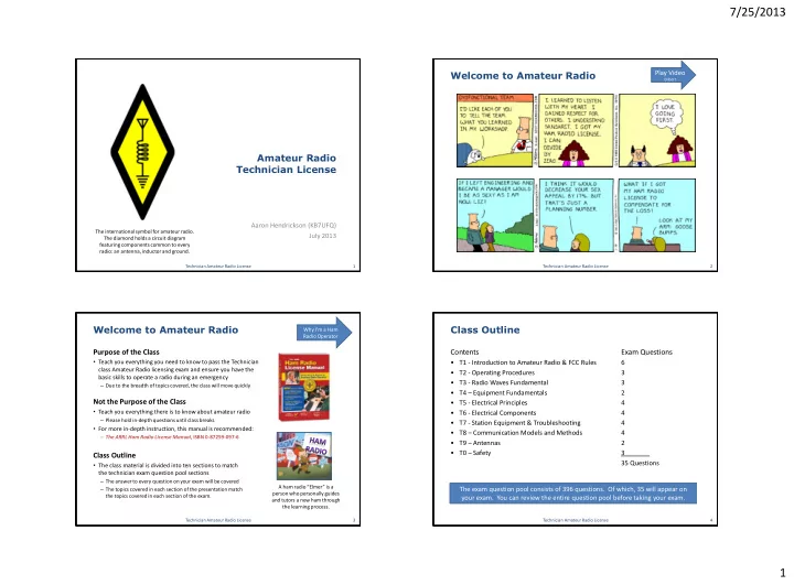
US Amateur Bands

  • Bands: The physical wavelength of the radio wave is

used to identify the band (or group of radio waves with similar characteristics)

– 2-meters is most common (144-148 MHz) – 70-centimeters is growing in popularity (420-450 MHz)

  • Technician class operators are allowed to transmit on

the bands shown to the right, which are VHF and UHF frequencies

  • 50.0 to 50.1 MHz and 144.0 to 144.1 MHz are

restricted to Morse Code communication only

  • Wavelengths above 10 meters (or frequencies below

30 MHz) are HF frequencies

Technician Amateur Radio License 45

Technician Class License Operating Privileges

Technician Class Amateur Radio License 44

Very Low Frequency (VLF); Low Frequency (LF); Medium Frequency (MF), High Frequency (HF); Very High Frequency (VHF), Ultra High Frequency (UHF); Super High Frequency (SHF); Extremely High Frequency (EHF) 3 kHz 30 kHz 300 kHz 3 MHz 30 MHz 300 MHz 3 GHz 30 GHz 300 GHz

VLF LF MF HF VHF UHF SHF EHF Low Frequencies Long Wavelengths High Frequencies Short Wavelengths

VHF TV FM UHF TV Cell Phone AM Shortwave Radio Frequency (RF signals) Audio

Polarization

  • Polarization is the orientation of the electric field of the radio wave.

A radio wave can be horizontally, vertically, or circularly polarized.

– Holding transceiver so that the antenna is vertical maximizes performance. This happens because the polarization of the radio waves match the antenna. – When VHF/UHF antennas are misaligned, the received signals can be dramatically reduced, as much as 100 times. – Horizontal antenna polarization is normally used for long-distance weak- signal CW and SSB contacts using the VHF and UHF bands. Horizontal polarization is preferred because it results in lower ground losses when the wave reflects or travels along the ground.

  • For practical purposes, what factors most contribute to how far I

can talk on my radio?

– Wavelength of the radio wave – Signal strength or power – Obstructions in the radio wave path (buildings, hills, etc.) – Height and type of your transmitting antenna – Polarization of the radio waves (polarization matters)

Technician Amateur Radio License 46

Inexperienced users do not hold their radios vertical and substantially reduce their transmission distance by misaligning the radio wave polarization.

Propagation

  • Propagation is the movement of

radio waves.

– Radio waves spread out from an antenna in straight lines unless reflected or diffracted along the way, just like light. – The earth seems less curved to radio waves than to light, therefore, VHF and UHF radio signals usually travel about 1/3 farther than the visual line

  • f sight between two stations.
  • The strength of radio waves

decrease as they travel farther from the transmitting antenna

  • Radio horizon is the most distant

point to which radio signals can be sent directly without reflection

– In most cases it is the point where radio signals between two points are blocked by the curvature of the earth.

Technician Amateur Radio License 47

VHF and UHF radio waves are diffracted around the sharp edges of a solid object, such as a building, hill or other

  • bstruction. Some signals appear behind the obstruction as a

result of interference between waves that are bent in different ways around the obstruction. The resulting interference pattern creates shadowed areas where little signal is present.

Knife Edge Propagation

Propagation and the Ionosphere

Altitude (miles)

Troposphere

170 140 70 60 30 6

Stratosphere D Layer E Layer F1 Layer F2 Layer

Ionosphere is composed

  • f these layers
  • Ionosphere is formed by solar ultraviolet (UV)

radiation.

– The UV rays knock electrons loose from air molecules, creating weakly charged layers at different altitudes. These layers can absorb or refract radio signals, sometimes bending them back to the earth.

  • Reflecting Radio Waves: The ability of the

ionosphere to diffract or bend radio waves is dependent on numerous factors:

– Frequency of the radio wave – Intensity of solar radiation – Daytime or nighttime

  • Meteor Scatter Propagation: A meteoroid

burring up in the ionosphere leave a meteor trail of ionized gas that can reflect radio signals.

– The best band for meteor scatter is 6 meters and contacts can be made at up to 1500 miles.

F1 and F2 combine at night improving the ionospheres ability to reflect radio waves

Technician Amateur Radio License 48

slide-13
SLIDE 13

7/25/2013 13

Sky Wave Propagation

  • VHF and UHF signals are not normally heard over long distances because their signals are not

usually reflected by the ionosphere

– As such, most propagation at VHF and higher frequencies is line-of-sight.

  • HF Radio waves can be completely bent back towards the earth by the ionosphere’s F layers

this is known as sky wave propagation or “skip”

– When skipping the polarization of the original signal can be randomized

Technician Amateur Radio License 49

Sky Wave Propagation

  • Open and Closed Bands: When sky-wave propagation is possible between two points the band

is said to be “open”. If not, the band is “closed”.

– Because the ionosphere depends on solar radiation to form, areas in daylight have a different ionosphere above them than do those in nighttime areas. This can make DXing (making long distance contacts) very interesting.

  • Maximum usable frequency

(MUF) is the highest frequency signal that can be reflected back to the Earth.

– The MUF rises as the sun illuminates the ionosphere. That’s why the upper HF bands, such as a 10 meters, are more likely to be open during the day.

  • Lowest Usable Frequency

(LUF) is the lowest frequency that can travel between points without being absorbed in the Ionosphere.

Technician Amateur Radio License 50

Sporadic-E, Aurora and Tropospheric Propagation

  • Sporadic-E Propagation: From time to time, often during the sun’s sunspot cycles, patches of the

ionosphere's E-layer can become sufficiently ionized to reflect VHF and UHF signals back to earth.

– This most common during early summer and mid-winter months. Sporadic-E propagation supports long- distance communication on VHF and UHF bands not possible under normal conditions.

  • Aurora Propagation: The northern lights (aurora) is the glow from thin sheets of charged

particles, which can also reflect UHV and VHF signals. But because they are constantly changing, the reflected signals change strength quickly and often become distorted.

  • Tropospheric Propagation (Tropo): Weather fronts or temperature inversions can assist the

propagation of frequencies at or above VHF.

– Layers of air with different characteristics can also form structures called ducts that can guide radio waves for long distances (300 mile paths are not uncommon).

Ground Reflection Sporadic-E Sporadic-E

Technician Amateur Radio License 51

Multi-Path and Picket Fencing

  • Multi-path is the phenomenon that occurs when radio signals arrive at a receiver after taking

different paths from the transmitter.

– The radio signals can interfere with each other (error rates increase and signal clarity decreases) – Can cause irregular fading of signals during times of generally good reception – If another station reports your signal were strong a moment ago but are now distorted, try moving a few feet, as random reflections may be causing multi-path distortion – When trying to reach a distant repeater, with obstructions blocking the line sight path, a directional antenna can help you find a path that reflects the signal to the repeater

Technician Amateur Radio License 52

  • Picket Fencing is the term commonly used

to describe the rapid fluttering sound sometimes heard from mobile stations that are moving while transmitting.

– Typically picket fencing happens because multi- path is occurring

  • Receiver Overload: Strong signals can
  • verload a receiver causing undesired

signals to be heard often in the form of sudden bursts of tones or fragments of different conversations

Picket Fencing describes the rapid fluttering sound sometimes heard from mobile stations.

slide-14
SLIDE 14

7/25/2013 14

T4: Equipment Fundamentals

Common Equipment Terms

  • Transmitter is used to convert sounds into radio signals
  • Receiver is used to convert radio signals into sounds we can hear.
  • Transceiver is a receiver and a transmitter in one unit.
  • Amplifier is used to increase the power (watts) of a transmitter.
  • Microphone connects to the transmitter in a amateur radio station

– Some connectors include push-to-talk and voltages for powering the microphone – If the microphone gain is set too high it may cause the signal to become distorted

  • Speakers convert electric signals into sound waves

– When microphone is too close to the speakers audio feedback will occur – Headphones are a popular alternative to speakers especially when trying to hear

  • r “copy” transmissions in a noisy area
  • Power Supply is used to convert alternating current from a wall outlet into

low-voltage direct current.

  • Regulated power supply protects equipment from voltage fluctuations

(output voltage only varies a small amount across differing loads).

Technician Amateur Radio License 53

Transmitter + Receiver = Transceiver Examples

  • f Power

Supplies: Extendable Speaker/Mic

Station Setup and Operation

  • Computer sound cards provides audio to the

microphone input and converts received audio to digital form

– For some digital modes, a sound card connects a radio to a computer for data transmissions

  • Terminal Node Controller (TNC) is connected

between the transceiver and computer terminal in a packet radio station

– Packet radio stations do not require use of the microphone

  • Automatic Position Reporting System (APRS) is a

system by which amateurs can report their position automatically by radio to central servers from which their locations can be observed.

– This is very helpful for search and rescue efforts – To send automatic location reports, in addition to your radio you need a GPS (Global Positioning System) receiver attached to the TNC (Terminal Node Controller), which is a device that acts as an interface between a computer and a radio.

Technician Amateur Radio License 54

Common Operating Terms

  • Variable Frequency Oscillator: Frequency can be changed by

entering the frequency directly on the keypad, using the “up” and “down” buttons, or by turning the VFO knob

  • Receiver Incremental Tuning (RIT) is a fine tuning control that

allows the operator to adjust the receiver frequency without changing the transmitter frequency (also known as clarifier)

– Example: this control could be used if the voice pitch of a single- sideband signal seems too high or low

  • Gain is the amount of amplification of a signal in a piece of

equipment, such as AF Gain (volume) or RF Gain (sensitivity – HF radios only)

– If the microphone gain is set too high it may cause the signal to become distorted

  • Squelch is the circuitry that mutes a receiver when no signal is

received

  • Memory Channels enable quick access to a favorite frequency
  • n your transceiver
  • Repeater Offset is the difference between the repeater’s

transmit and receive frequencies

Technician Amateur Radio License 55

Interference

Various Types of Interference

  • Front-end overload is interference to a receiver caused by strong

signals from a nearby source (the signals cause the receiver’s sensitive input circuitry “front end” to be overloaded)

  • Television Interference

– When an amateur is transmitting a break in a cable television transmission line may cause TV interference or amateur receiver interference

  • Telephone Interference

– Be aware that some telephones are not equipped with adequate interference protection when manufactured

Technician Amateur Radio License 56

  • Alternator Interference

– A vehicles alternator is the source of a high-pitched whine that varies with engine speed in a mobile transceiver’s receive audio – Your car’s alternator is what generates electricity and recharges your car battery

Ensure Proper Grounding to Help Reduce Interference

  • When connecting the power cable for a mobile transceiver, the negative power

connection should be made to the battery or engine block ground strap

  • To have the lowest possible impedance to RF current, connect to a ground rod using a

wide conductor (such as flat strap) that has more surface area, or use a heavy solid wire.

Even if your transmissions are causing front end overload in your neighbor’s television receiver the neighbor is responsible for taking care of the interference, but the courteous thing to do is to help your neighbor resolve the problem

slide-15
SLIDE 15

7/25/2013 15

Removing Interference

Various Types of Filters Can be Used to Remove Unwanted Signals or Interference

  • Filter may be installed at the transmitter to reduce spurious emissions

– A filter may be installed between the transmitter and the antenna to reduce harmonic emissions – Wide filters (around 2400 Hz) are use for SSB (single side band) on phone (voice communication) – Narrow filters (around 500 Hz) are used for Morse code and data mode reception. – Having multiple filters available allows you to reduce noise or interference by selecting a filter with just enough bandwidth to pass the desired signal.

  • Notch filter or Band-reject Filter removes a very narrow range of frequencies, usually from a

receiver’s audio output to remove continuous tones.

– Band-reject filter can be connected to a TV receiver as the first step in trying to prevent RF overload from a nearby 2 meter transmitter

  • Ferrite choke reduces RF current flowing on the shield side of an audio cable
  • Noise blanker senses sharp buzzing pulses from power lines, motors, or vehicle ignition

systems and temporarily mutes the receiver during the pulse

Technician Amateur Radio License 57 Frequency Signal Passed

More Less Lower Higher

High-Pass Filter

Pass Reject Frequency Signal Passed

More Less Lower Higher

Band Pass Filter

Pass Reject Reject Frequency Signal Passed

More Less Lower Higher

Low-Pass Filter

Pass Reject Signal Passed

Lower Higher

Notch Filter

Pass Reject Pass

T5: Electrical Principles

Electricity Basics

  • Current is the flow of electrons; negatively charged

atomic particles.

– Represented by the symbol “I” or “I” – Measured in amperes (A or amps) with an Ammeter

  • Voltage is the electro-motive force that causes

electrons to move.

– Represented by the symbol “E” or “e” – Measured in volts (V or v) with a Voltmeter – Most mobile radios (transceivers) require 12 volts

  • Power is the product of current and voltage. It is

the rate at which energy is generated or consumed.

– Represented by the symbol “P” – Measured in watts (W)

P = I * E Power = Current * Voltage (Watts = Amps * Volts)

=

Technician Amateur Radio License 58 Voltage is analogous to pressure in a water pipe and current is analogous to water flow. You can have pressure without flow, but you cannot have flow without pressure

Don’t Let the Electrical Theory Monster Get You! Electricity is as easy as P=I*E.

Alternating Current & Direct Current

  • Direct Current (DC) is current that flows in one direction at all times.
  • Alternating Current (AC) is current that regularly reverses direction.

Technician Amateur Radio License 59

Magnitude and Direction Time

Steady Direct Current Alternating Current

Resistance and Decibels

  • Resistance is opposition to current flow in
  • rdinary conductors.

– Represented by the symbol “R” – Measured in ohms (Ω, the Greek letter omega)

  • Conductors are materials in which

electrons flow easily.

– Metals, salt water, human body

  • Insulators are materials that resist or

prevent the flow of electrons.

– Glass, ceramics, wood, plastics

  • Ohm’s Law states that resistance is the

ratio of applied voltage to the resulting current.

– Resistance = Voltage / Current

Technician Amateur Radio License 60

R = E / I Resistance = Voltage / Current Ohms = Volts / Amps

Revisit Basic Definitions:

  • Radio waves are electromagnetic waves that

travel through space at the speed of light

  • Frequency is the number of complete cycles of

an alternating current that occur per second.

– Measured in Hertz; “RF” (radio frequency) is an abbreviation that refers to radio frequency signals

  • f all types

Decibels:

  • Antenna gain is listed in terms of decibels (db).

Decibels follow a logarithmic scale where 3 dB = 2x the power, 6 dB = 4x the power, 9 dB = 8x the power, etc.

Decibels Power 3 dB 2x the power 6 dB 4x the power 9 dB 8x the power 12 dB 16x the power

Exam Question Pool:

1) What is the amount of change, measured in decibels (dB), of a power decrease from 12 watts to 3 watts? 2) What is the approximate amount

  • f change, measured in decibels

(dB), of a power increase from 5 watts to 10 watts? Answers: 6 dB; 3dB

slide-16
SLIDE 16

7/25/2013 16

Units and Measures

Technician Amateur Radio License 61

Prefix Symbol Multiplication Factor Tera T 10^12 = 1,000,000,000,000 Giga G 10^9 = 1,000,000,000 Mega M 10^6 = 1,000,000 Kilo k 10^3 = 1,000 Hecto h 10^2 = 100 Deca da 10^1 = 10 Deci d 10^(-1) = 0.1 Centi c 10^(-2) = 0.01 Milli m 10^(-3) = 0.001 Micro m 10^(-6) = 0.000001 Nano n 10^(-9) = 0.000000001 Pico p 10^(-12) = 0.000000000001

Exam Question Pool:

Milli: How many milliamperes is the same as 1.5 amperes? Kilo: How many volts are equal to one kilovolt? Micro: How many volts are equal to one microvolt? Pico: How many microfarads are 1,000,000 picofarads? Answers: 1500 milliamperes 1000 volts One-millionth of a volt 1 Microfarad

T6: Electrical Components

Key Terms and Definitions:

  • Resistor is the electrical component used to oppose the flow of

current in a DC circuit (much like a valve in a water pipe)

  • Potentiometer is another name for a variable resistor. It is
  • ften used as an adjustable volume control.

– Resistance is the electrical parameter controlled by a potentiometer

  • Capacitor stores energy in an electric field (consists of two or

more conductive surfaces separated by an insulator)

– Capacitance is the ability to store energy in an electric field (measured in Farads – named after Michael Faraday) – A capacitor is used together with an inductor to make a tuned circuit

  • Inductor stores energy in a magnetic field (usually composed of

a coil of wire) and smoothes out current changes

– Inductance is the ability to store energy in a magnetic field called (measured in Henrys – named after Joseph Henry)

  • Switch is an electrical component that is used to connect or

disconnect electrical circuits

  • Relay is a switch controlled by an electromagnet
  • Fuse is an electrical component that is used to protect other

circuit components from current overloads

Technician Amateur Radio License 62

1 6 8 6 8

Resistors Capacitors Inductors

Electrical Components

  • Transistors are electronic components that are capable
  • f using a voltage or current signal to control current flow

– Can be used as an electronic switch or amplifier (gain is the term that describe a transistor’s ability to amplify a signal) – Bipolar junction transistor is made of three layers of semiconductor material – FET stands for “Field Effect Transistor” (Field Effect Transistors have a gate electrode) – Bipolar transistors have an emitter electrode

  • Integrated circuit what is the name of a device that

combines several semiconductors and other components into one package.

Technician Class Amateur Radio License 63

2

Transistor Counts Double Every 18- 24 months in Integrated Circuits

Electrical Component Definitions

  • Diode is an electronic component that allows current

to flow in only one direction

– The two electrodes of a diode are the anode and cathode – A semiconductor diode’s cathode lead is usually identified with a stripe – LED stands for “Light Emitting Diode”. LEDs are commonly used as a visual indicator.

  • Rectifier changes an alternating current into a varying

direct current signal (a heavy-duty diode for large voltages)

  • Transformer is commonly used to change 120V AC

house current to a lower AC voltage for other uses

  • Regulator controls the amount of voltage from a power

supply (hence you will see “regulated” power supplies)

  • Coaxial Cables are commonly used to carry RF signals

between a radio and antenna

  • Meter is a device that displays signal strength on a

numeric scale

Technician Amateur Radio License 64

5

4

Close-up view of a silicon diode. The anode is at the right side; the cathode is at the left side (where it is marked with a black band). A square silicon crystal can be seen between the two leads. Singlephase polemount transformer steps the voltage down form the high voltage used in transmission line to 120/240 volts used in homes Step Up and Down Voltage Converter Transformer (220 vs. 110 AC)

slide-17
SLIDE 17

7/25/2013 17

Circuit Diagrams & Schematic Symbols

  • Electrical circuit schematic diagrams represent the way

components are interconnected (not the wire length or physical appearance of components)

  • Schematic symbols are the standardized representations of

the electrical components in an electrical wiring diagram.

65

1 2 3 4 5 1 2 3 4 5 1 2 5 4 3 6 7 8 9 10 1 2 5 4 3 6 7 8 9 10

1) Resistor 2) Transistor (controls the

flow of current)

3) Lamp (incandescent) 4) Battery 5) Ground

Those symbols in large font and highlighted in blue are in the exam question pool

1) AC Plug 2) Fuse

3) Single-pole single-throw switch 4) Transformer

5) Diode

6) Capacitor

7) Resistor

8) Light emitting diode 9) Variable Resistor

10) Zener Diode

1 2 3 4 1 2 3 4

1) Input 2) Variable Capacitor

3) Variable Inductor 4) Antenna

Battery Basics

  • Disposable Batteries: (Typically alkaline) batteries have a full charge voltage of 1.5V; whereas

rechargeable (Nickel-Cadmium & Nickel-Metal Hydride) have a voltage of 1.2V

– Brand Performance: Avoid Diehard (Sears); “Heavy Duty”, Royovac, Radio Shack, Panasonic, Walgreens, and “15 minute” rechargeable batteries. – Costco Batteries: Duracell batteries often outperform in low-drain devices while Energizer batteries

  • utperform in high-drain devices. Costco (Kirtland) batteries are nearly as efficient as Energizer & Duracell

(in some cases more efficient) at less than one third of the cost.

  • Rechargeable Batteries: Nickel-Metal Hydride, Nickel-cadmium, lead-acid, lithium-ion

– Lithium-ion batteries have the longest life, lowest weight, and retain their charge the longest – At local power rates, you can recharge 190 AA batteries for less than 10 cents

Technician Amateur Radio License 66

  • Battery Care:

– Do not store batteries in the fridge (this is an urban legend); Operating a battery at a temperature too hot or too cold dramatically reduces battery life – Store them in a cool dry location; Inspect batteries regularly; Some types require regular maintenance charges – Using a Smart Charger and slow charging your batteries (200 milliamps is often recommended) dramatically prolongs battery life – During emergencies alternative power sources include: 12 volt car batteries, solar panels, & bicycle generators Recommended NiCd and NiMH Charger: La Crosse Technology BC-700 Alpha Power Battery Charger $33.30 (from Amazon.com)

Maximization of Battery Energy Output

Technician Amateur Radio License 67

Example: 33 amp-hour battery

  • Assumes we only deplete battery

to 50% life

  • This chart shows you that if you power

something with your battery that takes 792 Watts or about 66 Amps (792W / 12V = 66Amps), then this battery will be dead after about 12 minutes.

  • It also shows you that if you power

something that requires only 20 Watts

  • f power or 1.65 Amps, your battery

will be dead after 1200 minutes (or 20 hours) of operation.

Watts x Minutes = Total Index 792 watts x 12 minutes = 9,504wm 20 watts x 1200 minutes = 24,000wm

19.8 Watts 792 Watts

Drawing current from batteries at the slowest rate needed maximizes energy output

T7: Station Equipment and Troubleshooting

  • Modulator is a circuit that combines a speech signal and an RF carrier (the process of

combining voice and RF signals is called modulation)

  • Detector is the stage in a receiver in which the modulation (voice, etc) is recovered from a

modulated radio frequency signal (converts RF signal to data or voice)

– Product detector is used to detect CW and SSB signals – A Discriminator is a detector used for FM signals (a circuit that demodulates FM signals)

  • Superheterodyne is the standard receiver in Amateur radio that shifts signals to a single fixed

intermediate frequency (IF) for amplification and demodulation. Unwanted signals can then be removed by applying filters.

  • Sensitivity is a receivers ability to detect weak signals. If a receiver is not sensitive enough a RF

preamplifier is installed between the antenna and receiver to increase its detection ability.

  • Selectivity describes the ability of a receiver to retrieve information from just the desired signal

in the presence of unwanted signals (discriminate between multiple signals)

  • Transverter is a device that converts signals so that transceiver can operate on another band.

– Example: a transverter is used to convert 222 Mhz signals to and from the 28 Mhz band (28 Mhz is available on all HF gear whereas 222 Mhz is not generally)

  • Multi-mode transceiver is capable of SSB, CW, and FM operation. Since SSB and CW use less

bandwidth, a multi-mode transceiver is useful for VHF weak-signal communication.

– An RF power amplifier increases the low-power output from a handheld transceiver

Technician Amateur Radio License 68

slide-18
SLIDE 18

7/25/2013 18

Station Equipment Diagrams

A Basic Radio Station is Made Up of a Transmitter and Receiver Connected to an Antenna with a Feed Line

1 = Transmitter 2 = Transmit / Receive Switch 3 = Receiver

Technician Amateur Radio License 69

1 2 3 Figure T5

ANTENNA POWER AMPLIFIER DRIVER 1 TELEGRAPH KEY

Figure T4

A Simple Morse Code Transmitter

1= Oscillator (produces a steady signal at one frequency)

  • Driver is an amplifier circuit to make signal stronger

(helps frequency remain stable)

  • Telegraph key is a Morse Code (CW) key that turns

amplifier on and off

  • Power Amplifier makes signal strong enough for

communication with other stations

1

Only those parts of the block diagram highlighted in blue are in the exam question pool

2

Transmitter Receiver Feed Line Antenna

Station Equipment Diagrams

A Single-conversion Superheterodyne Receiver (standard receiver for CW or SSB)

  • Mixer combines signals to produce an output

signal with a different frequency

– Existence of one mixer indicates this is a single conversion superheterodyne

1 = Product detector (recovers the voice, data from the modulated signal)

  • The product detector uses a beat frequency oscillator

because it can be adjusted to product different tones

  • r frequencies, called “beats” in the output signal

An FM receiver 1 = Frequency Discriminator (a detector

used for FM signals). It recovers voice from a modulated signal.

  • Limiter is a high-gain amplifier that removal all

amplitude variations from the signal, leaving only the frequency variations that represent the modulation of the signal.

Technician Amateur Radio License 70

Figure T6 MIXER INTERMEDIATE FREQUENCY AMPLIFIER 1 AUDIO AMPLIFIER OSCILLATOR BEAT FREQUENCY OSCILLATOR

Figure T7

ANTENNA RADIO FREQUENCY AMPLIFIER MIXER WIDE FILTER INTERMEDIATE FREQUENCY AMPLIFIER OSCILLATOR LIMITER BLOCK 1 AUDIO AMPLIFIER

Text in blue corresponds to questions from the exam question pool

What do to if you Experience Interference

  • What might be the problem if you are told your signal is distorted
  • r weak?

– Your transmitter may be slightly off frequency – Your batteries may be running low – You could be in a bad location

  • What should you do if you are told your FM handheld or mobile

transceiver is over deviating?

– Talk farther away from the microphone

  • What should you do a device in your neighbor’s home is causing

harmful interference to your amateur radio station?

– Ensure your station to ensure it meets the standards of good amateur practice – Work with your neighbor to identify the offending device – Politely inform your neighbor about the rules that require him to stop using the device if it causes interference

  • Part 15 of the FCC’s rules deal with unlicensed devices likely to

transmit or receive RF signals

  • What should you do if your neighbor reports that your radio

signals are interfering with something in his home?

– Check your station to ensure it meets the standards of good amateur practice

Technician Amateur Radio License 71

Fundamental overload is interference caused by very strong signals from a nearby source. Other causes of radio frequency interference include spurious emissions and harmonics

What do to if you Experience Interference

  • What should you do first if someone tells you that your station’s

transmissions are interfering with their radio or TV reception?

– Make sure that your station is functioning properly and that it does not cause interference to your own television

  • What could be happening if another operator tells you he is hearing a

high-pitched whine on the signals from your mobile radio?

– Noise on the vehicle’s electrical system is being transmitted along with your speech audio

  • Telephone Interference

– A transmitter’s signals can cause the telephone to act like a radio receiver

  • Installing an RF filter at the telephone can often remedy the interference

– Correcting Interference: The following are useful in correct radio frequency interference problems:

  • Snap-on ferrite chokes; Low-pass and high-pass filters; Notch and band-

pass filters

Technician Amateur Radio License 72 This high-pass filter goes between the TV and antenna

  • Digital Signals: Digital signals are advantageous over analog signals because many digital

signals can automatically correct errors caused by noise and interference

– If your signal if very garbled and breaks up, it may be that RF energy is getting into the microphone circuit and causing feedback – Bit Error Rate (BER) is the rate at which errors occur in a stream of digital data.

slide-19
SLIDE 19

7/25/2013 19

Standing Wave Ratio

  • Standing Wave Ratio (SWR) is a measure of how well a load is

matched to a transmission line. It is determined by the proportions of forward and reflected power and their subsequent interference patterns.

– A SWR meter reading of 1 to 1 indicates a perfect impedance match between the antenna and feed line (indicates no reflected power and maximum transmitting power). In practice, SWR is almost always greater than 1:1. – As more power is reflected, more interference patterns emerge and SWR increases – Antennas that are too short or too long for the frequency being used often have extreme feed point impedances, causing high SWR

  • Importance of SWR: High voltage caused by SWR can damage a

transmitter’s output circuits – At a SWR value of 2 to 1, protection circuits in most transmitters begin to

reduce transmitting power automatically in order to protect its output circuits (at 4 to 1, there is a significant impedance mismatch)

Technician Amateur Radio License 73

SWR Meter measures the standing wave ratio in a transmission line. – It is important to have a low SWR in antenna systems that use coaxial cable feedlines to allow the efficiency transfer of power and reduce loses – A loose connection in your antenna or feed line may cause erratic changes in SWR readings. – Directional wattmeter (rather than an SWR meter) can also be used to determine if your feedline and antenna are properly matched by reading forward and reflected power

Feed Lines and Impedance

  • Feed line is used to deliver the radio signals to or from the antenna.

– Power lost in a feed line is converted into heat

  • Weather Protection is Important for Feed lines:

– Failure of coaxial cables is most often related to moisture contamination – Losses can increase dramatically in older coaxial cables that are exposed to weather and sunlight for several years. – Ultraviolet light can damage the jacket and allow water to enter the cable. The outer sheath of most coaxial cables are black in color because black provides protection against ultraviolet damage – "air core" coaxial cables have a disadvantage when compared to foam or solid dielectric types, because they requires special techniques to prevent water absorption

  • Impedance: Feed lines have a characteristic impedance, which is a measurement of how

energy is carried by the feed line (example: blow through a small stray and big straw)

– Identical Impedances: The power carried by a feed line is transferred completely to an antenna when the antenna and feed line impedances are identical or “matched”.

  • If the feed line and antenna do not match, some of the power is reflected by the antenna (power

traveling to the antenna is forward power & power reflected by the antenna is reflected power). – Directional wattmeter as another instrument (in addition to an SWR meter) can determine if a feedline and antenna are properly matched

Technician Amateur Radio License 74

Helpful Equipment and Measuring Devices

  • Dummy load or dummy antenna is an accessory that allows

you to test or adjust transmitting equipment without sending a signal (or dummy load) out over the air

– Using a dummy load helps keep the air waves free from test related transmissions and interference

  • Antenna Analyzer is used to determine if an antenna is

resonant at the desired operating frequency

Technician Amateur Radio License 75

  • Ammeter is an instrument used to measure electric current

– Usually connected in series with the circuit

  • Voltmeter is an instrument that measures electric potential or electromotive force

– Correct way to connect a voltmeter to a circuit is in parallel with the circuit

  • Ohmmeter is an instrument used to measure resistance

– IF the ohmmeter initially indicates a low resistance and then shows increasing resistance with time, the circuit likely contains a large capacitor – Ensure the circuit is not powered when measuring circuit resistance with an ohmmeter

  • Multimeter is commonly used to measure voltage and resistance

– Attempting to measure voltage when using the resistance setting might damage a multimeter

  • Solder:

– Rosin-core solder is the best solder for radio and electronic use. – Cold solder joints have a grainy or dull surface (so don’t touch the solder until it looks dull and grainy)

T8: Communication Models & Methods

  • Modulation is combining a radio signal with an information signal

– The basic principle of radio communication is combining a radio wave (carrier) with an information signal and transmitting it. A receiver separates the two.

  • Frequency-Modulation (FM) is the process of adding information to an RF signal (or carrier) by

varying its frequency characteristics.

– FM is the type of modulation most common in the VHF and UHF bands and is used for voice repeaters

76

  • Modulation: Adding information to the

carrier creates sidebands

– This requires more bandwidth. – Transmitter power is spread across this bandwidth.

  • An unmodulated radio signal (carrier)

requires narrow bandwidth

– The carrier contains no audio information – By using Morse code even carriers can be used to communicate

Technician Amateur Radio License

slide-20
SLIDE 20

7/25/2013 20

Single Side Band

  • Single Sideband (SSB) is a form of double-sideband amplitude modulation in which one

sideband and the carrier are removed.

– SSB is a common mode of voice modulation used for long distance and weak signal contacts on the VHF and UHF bands. – Primary advantage of SSB is that it uses much less bandwidth than FM signals

  • A SSB voice signal uses between 2 and 3 kHz of bandwidth, FM 5 to 15 kHz

– The Upper sideband (right) is normally used for 10 meter, VHF and UHF SBB communications

Technician Amateur Radio License 77

  • By filtering out the carrier (center) and
  • ne sideband (left), we save spectrum

and concentrate our RF energy into a narrower bandwidth (right). SSB is therefore more efficient.

– The carrier contains no audio information – The sidebands contain duplicate audio information

Transmission Bandwidth

Technician Amateur Radio License 78

  • Bandwidth Requirements:

– CW (Morse Code) has a very narrow bandwidth (~150 Hz) – A SSB voice signal uses between 2 to 3 kHz of bandwidth, FM 5 to 15 kHz – The normal bandwidth required for a conventional fast-scan TV transmission (video and audio) on the 70- centimeter band is ~6 MHz

  • Morse Code: Even with all of the communication methods based on frequency modulation,

Morse Code endures

– Due to their short bursts of energy, Morse Code transmissions can often travel farther and be received better than by modulated phone (speech) transmissions

  • Most repeaters send their station IDs in Morse Code
  • Morse code send and receive speed varies widely among amateurs

– The recommended sending speed is the speed at which you can receive

Play Video

Jay Leno 150 Hz

Satellite Operation

  • Usage: Any amateur whose license allows them to transmit on the satellite uplink frequency may

use the satellite (there are more than a dozen active Amateur Radio Satellites)

  • Benefit: Use of amateur radio satellites extend transmission ranges and often allow you to talk to
  • ther amateur radio operators in foreign countries

– As a technician licensed radio operator, you are also allowed to make contact with astronauts on the International Space Station using amateur radio frequencies – As always, use the minimum amount of power needed to complete the transmission

  • Satellite Terms:

– Satellite beacon is a signal from the satellite that contains information about it – Low Earth Orbit: Most satellites are not in geosynchronous orbit, meaning that they are not overhead all the

  • time. Rather, most are in “Low Earth Orbit” (LEO), meaning they are overhead only a portion of their orbit.
  • Satellite tracking program can help you determine when you can access an amateur satellite.

– Satellite sub-band is the portion of a band where satellite operations are permitted

  • Example: 435 to 438 MHz is the satellite sub-band on 70 centimeters.

– Doppler shift is a change in signal frequency caused by motion through space. This can make tuning into and transmitting to a satellite challenging. – AMSAT (Amateur Satellite Corp.) is the group that manages many of the amateur satellite programs. – FM Packet is a commonly used method for sending signals to and from a digital satellite – U/V Mode: Operating in “mode U/V” means the satellite uplink is the 70cm band and the downlink in the 2 meter band – Spin Fading: Signal fading caused by rotation of the satellite and its antennas

Technician Amateur Radio License 79

Special Operations

  • Radio direction finding is the

method used to locate sources of noise interference or jamming. Also known as “fox hunting.”

– A directional antenna is useful in tracking down offending transmissions

  • r for hidden transmitter hunts

– Grid locator is a letter-number designator assigned to a geographic location

  • Field Operation Supplies: extra

battery pack or cable to connect to an external battery, external antenna, listing of repeater frequencies in your area

– Combination headset and microphone are also sometimes valuable – External antennas make signals from a hand-held radio stronger than possible with standard “rubber-duck” antennas

Technician Amateur Radio License 80

Directional Antenna Transmitting on a radio without a license is known as “bootlegging”

  • r “pirating”.
slide-21
SLIDE 21

7/25/2013 21

Special Operations

  • Contesting is a popular operating activity where one contacts as many stations as possible

during a specified period of time

– Good procedure when contacting another station in a radio contest is to only send the minimum information needed for proper identification and the contest exchange

  • Special Event Station is a temporary station that operates in conjunction with an activity of

special significance.

– A temporary “1 by 1” format (letter-number-letter) call sign can be assigned for operations in conjunction with an activity of special significance to the amateur community

Technician Amateur Radio License 81

  • Radio Control Devices (such as remote control cars,

planes, boats, helicopters, etc.) – Amateurs may transmit radio control signals (called telecommand) with an output power of up to 1 watt

  • This allows licensed amateur radio operators to avoid

congested non-licensed frequencies near 27, 72 and 75 MHz when using their remote control devices

  • Since no call sign is used to identify the transmission, the

FCC requires that the amateur display his or her name, call sign and address on the radio control transmitter

Internet and EchoLink

  • Gateway is the name of an amateur station that is used to connect other amateur stations to

the Internet.

  • Voice over IP (VoIP)

– Echolink is a system of linking repeaters and computer-based users by using the VOIP (Voice-Over- Internet-Protocol).

  • Any licensed amateur radio operator may operate on the Echolink system
  • Allows computer-to-radio linking for voice transmission

– Internet Radio Linking Project (IRLP) is a system of linking two or more amateur stations using VOIP.

  • To select a specific IRLP node use the keypad to transmit the IRLP node numbers
  • An active list of nodes using VOIP can be found in a repeater directory or on the Internet.

– Internet Tone: When someone is using and internet linked station you will often hear a brief tone before the transmission

  • Example: If you a listening and hear a brief tone followed by a station from Russia calling CQ on a 2-

meter repeater than the Russian station is an Internet linked DX (distant station) station

Technician Amateur Radio License 82

Echolink via Internet

Great Distance

Common Amateur Emission Types

  • Emission privilege is permission to communicate using a particular mode, such as phone, CW,

data, or image.

  • For a technician licensee, mode restrictions are straightforward.

– Bottom of 6-meters and 2-meters are restricted to CW only – Straight Key, Electronic Keyer, Computer Keyboard can all be used to transmit CW in the amateur bands – The segment of the 1.25-meter band from 219-220 MHz is restricted to digital message forwarding only

Technician Amateur Radio License 83

CW (Continuous Wave) Morse Code Data or “Digital Modes” Computer-to-computer communication modes Image (TV) Television (fast-scan & slow-scan) and fax Phone (Voice) Speech or voice communications Pulse Communications using a sequence of pulses who characteristics are modulated in order to carry information RTTY (Radioteletype) Keyboard to keyboard. Narrow-band, direct-printing telegraphy received by a computer sound card SS Spread-spectrum communications in which the signal is spread

  • ut over a wide band of frequencies

Test Transmissions containing no information

Digital Non-Voice Communications

  • Digital communications are computer to computer

communication (transforming the 1s and 0s of data into tones)

– Examples: Packet, PSK31, MFSK – Parity bit is an extra code element used to detect errors in received data

  • Packet radio is a system of digital communication whereby

information is broken into short bursts (or packets)

– For example, in the 219-220 MHz frequency range an operator may use data emission modes such point-to-point digital message forwarding – All of the following may be included in packet transmissions

  • A check sum which permits error detection
  • A header which contains the call sign of the station to which the information

is being sent and an automatic repeat request in case of error

  • Phase Shift Keying (PSK) is a popular digital mode. PSK is a

digital modulation that conveys data by changing the phase of the reference signal (the carrier wave).

– PSK31 is a low rate data transmission mode and is the most popular keyboard-to-keyboard mode on HF (similar to instant messenger but

  • ver your radio)
  • Although it is not very fast, it works well in noisy conditions
  • Most amateurs use the DigiPan software when communicating via PSK31.
  • The software to use PSK31 is free at www.digipan.net

Technician Amateur Radio License 84

  • Data modes are computer-to-

computer communications, such as by packet radio or radioteletype (RTTY), which can be used to transmit and receive computer characters, or digital information.

  • Automatic Position Reporting

System (APRS) is a system by which amateurs can report their position automatically by radio to central servers.

slide-22
SLIDE 22

7/25/2013 22

Television Communication

  • Slow Scan Television is a television system used

by amateurs to transmit pictures within a signal bandwidth allowed on the HF/VHF/UHF bands.

– It takes ~8 seconds to send a signal black and white SSTV frame, and up to 4 ½ minutes for color frames – Slow Scan TV (SSTV) is typically used on 20 meters (HF); however, it can be transmitted on a VHF/UHF (typically 2-meter) repeater if the repeater operator authorizes it.

  • Fast Scan Television: In addition to slow scan

television (SSTV), amateur radio operators are also allowed to transmit fast scan television signals

– ATV (Amateur Television) is the hobby of transmitting broad-cast quality video and audio

  • ver amateur frequencies

Technician Amateur Radio License 85 The text above reads: “JA9HZY (Japanese call sign) thanks for the nice conversation (QSO) so best regards (73) to you from HL1AQ (South Korean call sign)”

  • NTSC is the term that denotes a standard analog fast scan color television signal and stands for

“National Television System Committee”

– NTSC transmissions occupy ~6MHz of bandwidth because it transmits 25 or 30 frames per second (SSTV requires 3 KHz of bandwidth)

T9: Antennas

Technician Amateur Radio License 86

  • Vertical Antenna consists of a single element mounted

perpendicular to the Earth’s surface.

– Quarter-wavelength vertical antenna length: Length (feet) = 234 / Frequency (MHz)

  • Example: The approximate length, of a quarter-wavelength

vertical antenna for 146 MH is 1.6 feet (19 inches) – In vertical antennas, 5/8 wavelength has an advantage over ¼ wavelength in that radiation patterns concentrate energy at lower angles – The electric field is perpendicular to the Earth on vertical antennas

  • Horizontal Antenna is mounted so the elements are

parallel to the Earth’s surface.

– The dipole antenna is the most common type of horizontal antenna

  • Antenna Gain: the gain of an antenna is the increase in

signal strength in a specified direction when compared to a reference antenna

  • Antenna tuner matches the antenna system impedance to

the transceiver's output impedance

Dipole Antennas

  • Dipole Antenna is an horizontal antenna which has two

symmetrical linear halves. It consists of a length of wire or tubing with a feed point at the center.

– Half wave dipole: the entire antenna is ½ wavelength long at the desired frequency – The total length of the antenna can be calculated by using the formula: Length (feet) = 468 / Frequency (MHz)

  • Example: The approximate length, in inches, of a 6

meter 1/2-wavelength wire dipole antenna is 112 inches (468/50 Mhz = 9.33 feet or 112 inches) – Shorten a dipole antenna to make it resonant on a higher frequency

½ wavelength by formula Coax Feed Point

Ground Dipole

Physical size of half-wave dipole antenna becomes shorter as frequency increases

Length (ft) = 468 / MHz

Technician Amateur Radio License 87

Dipole Radiation Pattern

In figure A, The length of the arrows indicated the relative strength of the radiated power in that direction. The dipole radiates best broadside or perpendicular to its length. In figure B, the 3-D pattern shows radiated strength in all directions.

Technician Amateur Radio License 88

slide-23
SLIDE 23

7/25/2013 23

Directional (or beam) Antennas

Technician Amateur Radio License 89

  • The Yagi, Quad, and Dish are all types
  • f directional or beam antennas

– Beam antennas concentrate signals in

  • ne direction

– Yagis and Quads are the two most widely used types of beam antennas

Yagi Antenna Quad Antenna

The radiation pattern of a typical, three-element Yagi antenna shows that most of the antenna’s energy is focused in one direction. The round pattern of the isotropic antenna (equal radiation in all directions) and the figure-eight pattern of the dipole are included for reference.

Yagi Antenna

Technician Amateur Radio License 90

  • Driven Element: Only one element actually

connects to the feed line, this element is known as the driven element

  • Gain is the concentration of radio signals in a

specific direction

– Gain only focuses power, it does not create power – Antenna gain is listed in terms of decibels (db). Decibels follow a logarithmic scale where 3 dB = 2x the power, 6 dB = 4x the power, 9 dB = 8x the power, etc.

Three Element Yagi Reflector Director Driven Element Supporting Beam or “Boom”

Direction To Station

Feed Point Coaxial Feedline

Feedlines and Coaxial Cable

  • Coaxial cable is a type of feed line with one conductor inside the other and both sharing a

concentric central axis.

– Coaxial is the most common feed line for antennas because it is easy to use and install. The impedance of common coaxial cable is 50 Ohms. Coaxial cables carry the radio signal between the center conductor and the inside surface of the braided shield (outer conductor)

  • Feedline Loss

– Having a low standing wave ratio (SWR) in an antenna system that uses coaxial cable feedline allows for the efficient transfer of power and reduces loses. To prevent an increase in feedline loss coaxial connectors exposed to the weather should be sealed against water intrusion – As the frequency of a signal passing through coaxial cable is increased the loss increases – A special type of coaxial feed line is called air-insulated hard line because its shield is made from a semi- flexible solid tube of aluminum or copper. This limits the amount of bending the cable can do, but also has the lowest loss of any type of coaxial feed line. – RG-8 cable has less loss at a given frequency and the smaller RG-58 cable (see chart below)

Technician Amateur Radio License 91

Single Shield Coaxial Cable

Insulation Outer Conductor (Braided Shield) Plastic Sheath (Jacket) Center Conductor

Coaxial Connectors

Several Types of Coaxial Connectors

  • The UHF series connectors (not to be

confused with ultra-high frequency in this case) also called PL259s are the most widely used for HF equipment

  • Above 400 Mhz, the type N connectors

are typically used.

Technician Amateur Radio License 92

Frequency Connectors HF UHF Connectors (PL259s most common) VHF Both UHF and Type N Connectors UHF Type N Connectors

PL259 Connector Type N Connector Coaxial connectors and adapters

Connectors Should Be Secure

  • A loose connection in an

antenna or a feedline may cause erratic changes in SWR readings

slide-24
SLIDE 24

7/25/2013 24

Rubber Duck Antennas

Technician Amateur Radio License 93

  • Rubber duck is the flexible antenna used

with most handheld radios

– More convenient size but not as effective as a full size antenna – When using a rubber duck antenna from inside your vehicle signals can be 10 to 20 times weaker than when you are outside of your vehicle

  • Popular alternative is the magnet mount
  • r window mount vertical antenna

Or

Vehicle Magnet Mount Antenna

Rubber Duck

T0: Safety

  • Health Hazards

– Radio waves that have a combination of signal strength and frequency can injure the human body by causing excessive power to be absorbed

  • Most stations simply are not capable of causing health hazards.

However, if someone accidentally touches an antenna while transmitting they can receive a RF burn injury

– Current flowing through the body can pose a health hazard as it heats the tissue, disrupts the electrical functions of cells and can cause involuntary muscle contractions

  • To guard against electrical shock at your station:

– Use three-wire cords and plugs for all AC powered equipment

  • 3-wire cords: Green is ground, black is hot; white is neutral

– Connect all AC powered station equipment to a common safety ground

  • Ground is a connection to the earth for electrical safety.

– Use a circuit protected by a ground-fault interrupter

  • Ground Fault Interrupter (GFI) is a interrupting circuit breaker that
  • pens a circuit when an imbalance of current flow is detected
  • GFI power outlets are required in most kitchens and bathrooms

Technician Amateur Radio License 94

GFI Outlet Neutral Hot Ground

Fuses and Peak Envelope Power

  • Fuse is a thin metal trip that melts when too much current

passes through it.

– A fuse protects your radio by interrupting power in case of an

  • verload

– Fuses are rated in amperes – If you use a higher amperage fuse than the intended by your radio, the excess current may cause a fire – A fuse or circuit breaker in series with the AC "hot" conductor should always be included in home-built equipment that is powered from 120V AC power circuits

Technician Amateur Radio License 95

Modulation Peak

Amplitude Time

  • Peak Envelope Power (PEP)

is the average power of an RF signal at its largest amplitude peak

– Most handheld radios transmit at 5 watts PEP – Mobile radios typically transmit between 40 and 100 watts PEP

Safety Precautions

  • Lightening

– Before the storm you should: stop using your radio equipment, unplug all power cords from AC outlets, disconnect antenna cables from your station – A lightening protection system for your amateur station can prevent fires

  • When installing an emergency disconnect switch ensure everyone knows where it is and how to use it

– It is good practice to ensure that connections are short and direct when installing ground wires on a tower for lightning protection. When using grounding conductors used for lightning protection sharp bends must be avoided – When installing devices for lightning protection in a coaxial cable feed line, be sure to ground all of the protectors to a common plate which is in turn connected to an external ground

  • Batteries

– A battery charged or discharged too quickly it can overheat, give off flammable gas, or explode – Hazards of conventional 12-volt battery storage include: short circuits, acid spills, and gas leaks (explosive gas can collect if not properly vented)

  • When the power is out you can connect your 12-volt battery to a car’s battery and run the engine to use the alternator

to recharge the battery

  • Power Supplies

– When a power supply is turned off and disconnected be cautious to not receive an electric shock from stored charge in large capacitors

  • Antennas

– Stainless steel hardware is preferred since the parts are much less likely to corrode – Never attach an antenna to a utility pole as it could come in contact with high-voltage power wires

Technician Amateur Radio License 96

slide-25
SLIDE 25

7/25/2013 25

Antenna Tower Installation

Tower Safety

  • Be sure your antenna complies with local height restrictions (especially

important when near airports)

  • Before putting up an antenna make sure people will not be able to

accidentally come into contact with it

  • Wear a hard hat & safety glasses to protect yourself from falling objects
  • Install the antenna in accordance with the manufacturer’s instructions
  • A gin pole is used to life tower sections or antennas

Technician Amateur Radio License 97

Tower Climbing

  • If any climbing is required, you should use a climbing harness and safety glasses
  • Always use an observer to assist. Before climbing arrange for a observer, inspect the tower for damage, and

make sure there are no storms approaching (always use an observer)

  • Looks for and stay clear of any overhead electrical wires

– If the antenna falls unexpectedly, no part of it should come closer than 10 feet to the power lines

  • A crank-up tower should never be climbed unless it is the fully lowered position

Always Use a Proper Ground

  • An adequate ground for a tower includes separate 8 foot long ground rods for each tower leg, bonded to the

tower and each other

  • Local electrical codes establish grounding requirements for an amateur radio tower or antenna

Radiation and Radio Frequency (RF) Exposure

  • Radiation: RF radiation is not the same as ionizing radiation from radioactivity because radio

frequencies are not nearly high enough to cause an electron to leave the atom (ionize). Instead VHF and UHF radio signals emit non-ionizing radiation.

– Milliwatts per square centimeter is used to measure RF radiation exposure

Technician Amateur Radio License 98

  • Factors of RF Exposure

1) Distance from the antenna to the person

  • At twice the distance from an antenna power

density is lowered to one-quarter of the value (increasing distance from antenna lowers power density in proportion to the square of the distance from the antenna)

2) Frequency and power level of the RF field

  • A human body absorbs more RF energy at

some frequencies than others

3) Radiation pattern of the antenna (beam antennas focus radiated power in one direction and decreases your power in

  • ther directions)

500 500 500 425 225 125 100 75 50 50 50 50 70 150 200 250 100 200 300 400 500 600 160 80 40 30 20 17 15 12 10 6 2 1.25 70 33 23 13 Band (Meters) Band (cm) Power (W)

Power Thresholds for RF Exposure Evaluation

  • Exposure Evaluation Required: 50 watts PEP at the antenna is the maximum power level that an

amateur radio station may use at frequencies above 30 MHz before an RF exposure evaluation is required (mobile and handheld stations are exempt from FCC exposure evaluation rules)

50 MHz has the lowest Maximum Permissible Exposure limit

Determining Compliance

Technician Amateur Radio License 99

Determining Compliance

  • You can determine if your station complies with FCC RF exposure guidelines by:

– Calculation based on FCC OET Bulletin 65 (Office of Engineering Technology)

  • This method uses tables and simple formulas to evaluate whether your station has the potential of

causing an exposure hazard – Calculation based on computer modeling – By measurement of field strength using calibrated equipment

  • To ensure your station stays in compliance with RF safety regulations you should re-evaluate

your station whenever an item of equipment is changed Duty Cycle and Radio Frequency (RF) Exposure

  • Duty cycle is a measure of the amount of time a transmitter

is operating at full output power. When referring to RF exposure, duty cycle is the ratio of on-air time to total

  • perating time of a transmitted signal

– Lower duty cycle reduces RF radiation exposures. Higher duty cycle increases a person’s exposure.

Commonly Accepted Safety Thresholds

  • 100 milliamperes is the lowest amount of electrical current

flowing through the human body that is likely to cause death

  • 30 volts is the lowest voltage that can cause a dangerous

electric shock (causes enough current to flow to be dangerous)

Current

(Milliamps)

Reaction <1 No perception 5 Faint tingle 6-30 Painful shock, loss of muscular control 50-150 Extreme pain, respiratory arrest; death is possible. 1000-4300 Muscular contraction and nerve damage; death likely 10,000+ Cardiac arrest, severe burns, Death probable

You Can Do it. Let the Adventure Begin.

Technician Amateur Radio License 100

Best Wishes on Your Exam.

  • Free online practice exams are available at the

following websites: (Note: You do not need to register at either

  • f these sites to take a practice exam)

– http://www.eham.net/exams/ – http://hamexam.org/

  • Online videos to brush up on specific exam sections:

– http://www.hameducation.com/technician/

I recommend you read through the course material one more time and successfully pass at least two practice exams before you take the real exam.